Run Data Platform in Minutes on VMware Cloud Director

Featured

Enterprise applications increasingly rely on large amounts of data, that needs be distributed, processed, and stored. Open source and commercial supported software stacks are available to implement a data platform, that can offer common data management services, accelerating the development and deployment of data hungry business applications, VMware has made it simple for cloud providers to offer, deploy and manage using Data Platform Blueprint.

Understand Validated Blueprint and Requirement for Data Platform

You can find validated blueprint designs in the Bitnami Application Catalog and VMware Marketplace, including blueprints for building containerized data platforms with Kafka, Apache Spark, Solr, and Elasticsearch.

These engineered and tested data platform blueprints are implemented via Helm charts. They capture security and resource settings, affinity placement parameters, and observability endpoint configurations for data software runtimes. Using the Helm CLI or KubeApps tool, Helm charts enable the single-step, production-ready deployment of a data platform in a Kubernetes cluster, covering automated installation and the configuration of multiple containerized data software runtimes.

Each data platform blueprint comes with Kubernetes cluster node and resource configuration guidelines to ensure the optimized sizing and utilization of underlying Kubernetes cluster compute, memory, and storage resources. For example, README.md covers the Kubernetes deployment guidelines for the Kafka, Apache, Spark, and Solr blueprint.

This Blueprint enables the fully automated Kubernetes deployment of such multi-stack data platform, covering the following software components:

  • Apache Kafka – Data distribution bus with buffering capabilities
  • Apache Spark – In-memory data analytics
  • Solr – Data persistence and search
  • Data Platform Signature State Controller – Kubernetes controller that emits data platform health and state metrics in Prometheus format.

These containerized stateful software stacks are deployed in multi-node cluster configurations, which is defined by the Helm chart blueprint for this data platform deployment, covering:

  • Pod placement rules – Affinity rules to ensure placement diversity to prevent single point of failures and optimize load distribution
  • Pod resource sizing rules – Optimized Pod and JVM sizing settings for optimal performance and efficient resource usage
  • Default settings to ensure Pod access security

Cloud Director Provider Configuration

Install and Configure VMware Cloud Director App Launchpad

App Launchpad is a VMware Cloud Director service extension which service providers can use to create and publish catalogs of deployment-ready applications. Tenant users can then deploy the applications with a single click, for App Launch Pad Install and Configure see Here , once App Launchpad is installed, configure it with Bitnami helm repository as below:

  • Log in to the VMware Cloud Director service provider admin portal.
  • From the main menu (), select App Launchpad
  • On the Settings tab, click on Helm Chart Repository
  • Click Add.
  • Add the required repository details.

Add DataPlatform Blueprint from Helm Chart Repository

  1. Log in to the VMware Cloud Director service provider admin portal.
  2. From the main menu (), select App Launchpad.
  3. On the Applications tab, click Add New.
  4. Select Chart Repository as the application source.
  5. Select the chart repository from which you want to import applications and click Next.
  6. Select the application and application version that you want to add and click Next.You can add multiple applications at once.
  7. Select an existing VMware Cloud Director catalog to which you add the application or create one, and click Next.
  8. Review the applications details and click Add.

Tenant Self-Service Deployment

Once Provider has published Data Platfrom blue prints to tenants, tenants can deploy those on Tanzu Kubernetes Cluster in self service way. so before deploying tenant must need to:

  • Create Tanzu Kubernetes Cluster with enough CPU and Memory to master and worker nodes, for this blog i created a four node worker cluster with 4 vCPU and 16 GB Memory.

Below are the minimum Kubernetes Cluster requirements for “Small” size data platform:

Data Platform SizeKubernetes Cluster SizeUsage
Small1 Master Node (2 CPU, 4Gi Memory)
3 Worker Nodes (4 CPU, 32Gi Memory)
Data and application evaluation, development, and functional testing
  • Create Default Storage Class – Once Tanzu Kubernetes Cluster created, create an default stoage class for Tanzu Kubernetes cluster using below sample yaml
kind: StorageClass
apiVersion: storage.k8s.io/v1
metadata:
  annotations:
    storageclass.kubernetes.io/is-default-class: "true"  <ensure true>
  name: vcd-disk-dev
provisioner: named-disk.csi.cloud-director.vmware.com
reclaimPolicy: Delete
parameters:
  storageProfile: "Tanzu01"  <your org VDC stroage policy>
  filesystem: "ext4"
  • Tenant Deploys Data Platform BluePrint – Now Tenant goes ahead in Cloud Director App launchpad and deploys Data Platform Blueprint using their choice of settings or with default settings
  1. Select DataPlatform Blue Print and click on Deploy
  2. Enter Application Name
  3. Select Tanzu Kubernetes Cluster on which tenant want to install data platform
  4. Click on “Launch Application”
  • This blue print bootstraps Data Platform Blueprint-1 deployment on a Kubernetes cluster using the Helm package manager.Once the chart is installed, the deployed data platform cluster comprises of:
    • Zookeeper with 3 nodes to be used for both Kafka and Solr
    • Kafka with 3 nodes using the zookeeper deployed above
    • Solr with 2 nodes using the zookeeper deployed above
    • Spark with 1 Master and 2 worker nodes
    • Data Platform Metrics emitter and Prometheus exporter

this process will also create required persistent volumes for the application, you can view the persistent volumes inside cloud director console, by going in to Tanzu Kubernetes cluster

or by going in to Organization VDC and click on “Named Disks”

The entire process takes some time, once done tenant should see all the pods are up and running, all the required volumes are created and attached and all the required services are exposed.

Testing the Kafka Cluster

(I am not Kafka expert took testing guidance from Internet, specially Platform9 website)

We are going to deploy a test client that will execute scripts against the Kafka cluster.Create and apply the following deployment:


$ vi testclient.yaml

apiVersion: v1
kind: Pod
metadata:
  name: testclient
  namespace: kafka
spec:
  containers:
  - name: kafka
    image: solsson/kafka:0.11.0.0
    command:
      - sh
      - -c
      - "exec tail -f /dev/null"

$ kubectl apply -f testclient.yaml

now lets use this “testclient" container, we will create the first topic, which we are going to use to post messages:

$ kubectl --kubeconfig kubeconfig-k8sdata -n 7f55bcb2-75f5-42db-b2a2-7c18e8ba5011 exec -ti testclient -- ./bin/kafka-topics.sh --zookeeper dp02-zookeeper:2181 --topic messages --create --partitions 1 --replication-factor 1

make sure you use the correct hostname for zookeeper cluster and the topic configuration. now lets verify that topic exists by using below command:

$  kubectl --kubeconfig kubeconfig-k8sdata -n 7f55bcb2-75f5-42db-b2a2-7c18e8ba5011 exec -ti testclient -- ./bin/kafka-topics.sh --zookeeper dp02-zookeeper:2181 --list

Now we can create one consumer and one producer instance so that we can send and consume messages. Open two putty shells and on first shell create consumer:

$ kubectl --kubeconfig kubeconfig-k8sdata -n 7f55bcb2-75f5-42db-b2a2-7c18e8ba5011 exec -ti testclient -- ./bin/kafka-console-consumer.sh --bootstrap-server dp02-kafka:9092 --topic messages --from-beginning

on second shell, create producer and start sending messages:

$kubectl --kubeconfig kubeconfig-k8sdata -n 7f55bcb2-75f5-42db-b2a2-7c18e8ba5011 exec -ti testclient -- ./bin/kafka-console-producer.sh --broker-list dp02-kafka:9092 --topic messages

>Hi
>How are you ?

On consumer shell, you should see these messages getting populated using data streaming platform.

Cloud Director with Container Service Extention along with App Launchpad offers easist way for providers to offer many monitizable services in multi-tenant environment and easiest way to deploy and consume these services for tenants. so providers what are you waiting for ?

Tanzu on Azure Native

Featured

VMware Tanzu Kubernetes Grid provides organizations with a consistent, upstream-compatible, regional Kubernetes substrate that is ready for end-user workloads and ecosystem integrations. You can deploy Tanzu Kubernetes Grid across software-defined datacenters (SDDC) and public cloud environments, including vSphere, Microsoft Azure, and Amazon EC2. in this blog post we will deploy Tanzu Kubernetes Grid 1.4 to Azure Native VMs.

Pre-requisite

  • Deploy a Client VM ,my case ubuntu VM, this VM will be the bootstrap VM for Tanzu, from where we will deploy management cluster in Azure, you can have one native Azure VM for this.
  • TKG uses a local Docker install to setup a small, ephemeral, temporary kind based Kubernetes cluster to build the TKG management cluster in Azure. you need Docker locally to run the kind cluster.
  • Download and Unpack the “Tanzu CLI” and “Kubectl” from HERE, on above VM in a new directory named "tkg" or "tanzu"
    • unpack using #> tar -xvf tanzu-cli-bundle-v1.4.0-linux-amd64.tar
    • After you unpack the bundle file, in your folder, you will see a cli folder with multiple subfolders and files
    • Install Tanzu CLI using #> sudo install core/v1.4.0/tanzu-core-linux_amd64 /usr/local/bin/tanzu
  • Unpack the kubectl binary using:
    • #> tar -xvf kubectl-linux-v1.21.2+vmware.1.gz
    • Install kubectl using #> sudo install kubectl-linux-v1.21.2+vmware.1 /usr/local/bin/kubectl
  • Run the following command from the tanzu directory to install all the Tanzu plugins:
    • #> tanzu plugin install –local cli all
    • #> tanzu plugin list

Configure Azure resources

In this section we will prepare Microsoft Azure for running Tanzu Kubernetes Grid, For the networking, i have prepared azure network as below:

  • Every Tanzu Kubernetes Grid cluster requires 2 Public IP addresses
  •  For each Kubernetes Service object with type LoadBalancer, 1 Public IP address is required.
  • A VNET with: (only required if using existing VNET else TKG can create all automatically)
    • A subnet for the management cluster control plane node
    • A Network Security Group on the control plane subnet with Allow TCP over port 22 and 6443 for any source and destination inbound security rules, to enable SSH and Kubernetes API server connections
    • One additional subnet and Network Security Group for the management cluster worker nodes.
  • Below is the high level network topology will look like when we deploy Tanzu Management Cluster:

Get Tenant ID

Make a note of the Tenant ID value as it will be used later by hovering over your account name at upper-right, or else browse to Azure Active Directory > <Your Org> > Properties > Tenant ID

Register Tanzu Kubernetes Grid as an Azure Client App & Get Application (Client) ID

Tanzu Kubernetes Grid manages Azure resources as a registered client application that accesses Azure through a service principal account. Below steps register your Tanzu Kubernetes Grid application with Azure Active Directory, create its account, create a client secret for authenticating communications, and record information needed later to deploy a management cluster.

  • Go to Active Directory > App registrations and click on + New registration.
  • Enter name and select who else can use it. leave Redirect URI (optional) field blank.
  • Click Register. This registers the application with an Azure service principal account

Make a note of the Application (client) ID value, we will use it later.

Get Subscription ID

From the Azure Portal top level, browse to Subscriptions. At the bottom of the pane, select one of the subscriptions you have access to, and make a note of Subscription ID.

Add a Role, Create and Record Secret ID

Click the subscription listing to open its overview pane and Select to Access control (IAM) and click Add a role assignment.

  • In the Add role assignment pane
    • Select the Owner role
    • Select to “user, group, or service principal
    • Under Select enter the name of your app, in my case “avnish-tkg”. It appears under Selected Members
  • Click Save. A popup appears confirming that your app was added as an owner for your subscription. You can also verify by going in to “Owned Application” section.
  • On the Azure Portal go to Azure Active Directory, click on App Registrations, select your “avnish-tkg” app under Owned applications.
  • Go to Certificates & secrets then in Client secrets click on New client secret.
  • In the Add a client secret popup, enter a Description, choose an expiration period, and click Add.
  • Azure lists the new secret with its generated value under Client Secrets. take a note of “Client Secret” value, which we will use later.

With All above steps, we will have four recorded values:

Subscription ID – XXXXXXX-XXX-4853-9cff-3d2d25758b70
Application Client ID – XXXXXXXX-6134-xxxx-b1a9-8fcbfd3ea189
Secret Value – XXXXX-xxxxxxxxxxxxxxxkB3VdcBF.c_C.
Tenant ID – XXXXXXXX-3cee-4b4a-a4d6-xxxxxdd62f0

we will use these values when we will create management cluster.

Create an SSH Key-Pair

To connect to management azure machine we must need to provide the public key part of an SSH key pair. you can use a tool "ssh-keygen" to generate one

  • #>ssh-keygen -t rsa -b 4096 -C “email@example.com
  • At the prompt Enter file in which to save the key (/root/.ssh/id_rsa): press Enter to accept the default
  • Enter and repeat a password for the key pair

Copy the content of .ssh/id_rsa.pub, which we will use in next section.

Accept Base VM image license

To run management cluster VMs on Azure, accept the license for their base Kubernetes version and machine OS by logging to azure cell and run below commands:

#> az login --service-principal --username AZURE_CLIENT_ID --password AZURE_CLIENT_SECRET --tenant AZURE_TENANT_ID

AZURE_CLIENT_ID, AZURE_CLIENT_SECRET, and AZURE_TENANT_ID are your avnish-tkg app's client ID and secret and your tenant ID, as recorded above

#> az vm image terms accept --publisher vmware-inc --offer tkg-capi --plan k8s-1dot21dot2-ubuntu-2004 --subscription AZURE_SUBSCRIPTION_ID

In Tanzu Kubernetes Grid v1.4.0, the default cluster image --plan value is k8s-1dot21dot2-ubuntu-2004.

Start the Installer Interface

On the machine on which you downloaded and installed the Tanzu CLI, run the

#> tanzu management-cluster create -b "IP of this machine:port" -u

b = binding with interface
u = for User Interface

On the local machine, browse to the above machine’s IP address to access the installer interface and then choose “Microsoft Azure” and click on “DEPLOY”

In the IaaS Provider section, enter the Tenant IDClient IDClient Secret, and Subscription ID values for your Azure account. we recorded these values in above pre-requisite section.

  • Click Connect. The installer verifies the connection and changes the button label to Connected.
  • Select the Azure region in which to deploy the management cluster.
  • Paste the contents of your SSH public key, ".ssh/id_rsa.pub“, into the text box.
  • Under Resource Group, select either the Select an existing resource group or the Create a new resource group radio button.

In the VNET for Azure section, select either the Create a new VNET on Azure or the Select an existing VNET radio button, in my case i am using existing VNET and Subnets which i had provisioned already.

To make the management cluster private, enable the Private Azure Cluster checkbox or leave it Untick. By default, Azure management and workload clusters are public. But you can also configure them to be private, which means their API server uses an Azure internal load balancer (ILB) and is therefore only accessible from within the cluster’s own VNET or peered VNETs.

In Management Cluster Settings section choose Development or Production tiles, use the Instance type drop-down menu to select from different combinations of CPU, RAM, and storage for the control plane node VM or VMs.

Under Worker Node Instance Type, select the configuration for the worker node VM

In the optional Metadata section, optionally provide descriptive information about this management cluster.

in Kubernetes Network section check the default Cluster Service CIDR and Cluster Pod CIDR ranges. If these CIDR ranges of 100.64.0.0/13 and 100.96.0.0/11 are not available, change the values under Cluster Service CIDR and Cluster Pod CIDR.

In Identity Management section, enable/disable Enable Identity Management Settings based on your use case.

In OS Image section, select the OS and Kubernetes version image template to use for deploying Tanzu Kubernetes Grid VMs, and click Next

In the Registration URL field, copy and paste the registration URL you obtained from Tanzu Mission Control or if you don’t have TMC access or URL, move next you can register it later if you want.

In the CEIP Participation section, optionally deselect the check box to opt out of the VMware Customer Experience Improvement Program and then Click Review Configuration to see the details of the management cluster that we have configured.

and finally click on Deploy Management Cluster.

Deployment of the management cluster can take several minutes, in my case around 12 minutes.

and finally, once everything is deployed and configured. your “Management Cluster Created”

The installer saves the configuration of the management cluster to ~/.config/tanzu/tkg/clusterconfigs with a generated filename of the form UNIQUE-ID.yaml. After the deployment has completed, you can rename the configuration file to something memorable, 

if you go to azure portal, you should see three control plane VMs, for with names similar to CLUSTER-NAME-control-plane-abcde, one or three worker node VMs with name similar to CLUSTER-NAME-md-0-rh7xv, Disk and Network Interface resources for the control plane and worker node VMs, with names based on the same name patterns.

At this point we can see management cluster deployed successfully, now we can go ahead and create workload clusters based on your requirement easily. Tanzu allows to deploy and manage Kubernetes cluster on vSphere, on VMware on public clouds and native public cloud AWS and Azure native, in next post i will deploy Tanzu on AWS.

Code to Container with Tanzu Build Service

Featured

Tanzu Build Service uses the open-source Cloud Native Buildpacks project to turn application source code into container images. Build Service executes reproducible builds that align with modern container standards, and additionally keeps images up-to-date. It does so by leveraging Kubernetes infrastructure with kpack, a Cloud Native Buildpacks Platform, to orchestrate the image lifecycle. Tanzu Build Service helps customers develop and automate containerized software workflows securely and at scale.

In this post Tanzu Build Service will monitor git branch and automatically build containers with every push. Then it will upload that container to your image registry for you to pull down and run locally or on Kubernetes cluster

Tanzu Build Service Installation Pre-requisite

  • Before we install Tanzu Build Service, you must ensure we have a Kubernetes cluster and ensure that all worker nodes have at least 50 GB of ephemeral storage allocated to them and also ensure your Kubernetes cluster is configured with default StorageClass

To do this on Tanzu Kubernetes Grid Service, mount a 60GB volume at /var/lib to the worker nodes in the TanzuKubernetesCluster resource that corresponds to your TKGs cluster. I have used below yaml content for mounting volumes while creating Tanzu Kubernetes cluster.

storage:
      classes:
      - tanzu01
      - tkgontkgs
      defaultClass: tkgontkgs
  topology:
    controlPlane:
      class: best-effort-medium
      count: 1
      storageClass: tkgontkgs
      volumes:
      - capacity:
          storage: 60Gi
        mountPath: /var/lib

    workers:
      class: best-effort-medium
      count: 3
      storageClass: tkgontkgs
      volumes:
      - capacity:
          storage: 60Gi
        mountPath: /var/lib
  • Ensure you have access to an existing container registry or install one using this guidance, this will be used to install Tanzu Build Service and store the application images that will be created by build process.
  • Also on a client VM from where you will connect to your Kubernetes cluster, install “docker cli” as well as install below tools , if you need guidance to install these tools, check Here
  • Install kapp, this is a deployment tool that allows users to manage Kubernetes resources in bulk.
  • Install ytt, this is a templating tool that understands YAML structure.
# wget -O ytt https://github.com/vmware-tanzu/carvel-ytt/releases/download/ v0.35.1/ytt-linux-amd64
#chmod +x ytt
#mv ytt /usr/local/bin/ytt
  • Install kbld,this is tool that builds, pushes, and relocates container images.
#wget -O kbld https://github.com/vmware-tanzu/carvel-kbld/releases/downloa d/v0.30.0/kbld-linux-amd64
#mv kbld /usr/local/bin/kbld
#chmod +x /usr/local/bin/kbld
  • Install kp, it controls the kpack installation on Kubernetes, download the kp CLI for your operating system from the Tanzu Build Service page on Tanzu Network.
#mv kp-linux-0.3.1 /usr/local/bin/kp
#chmod +x /usr/local/bin/kp
  • Install imgpkg, it is a tool that relocates container images and pulls the release configuration files.
#wget -O imgpkg https://github.com/vmware-tanzu/carvel-imgpkg/releases/dow nload/v0.17.0/imgpkg-linux-amd64
#mv imgpkg /usr/local/bin/imgpkg
#chmod +x /usr/local/bin/imgpkg
  • and finally target the Kubernetes Cluster on which you want to install “Tanzu Build Service” using :
#kubectl config use-context <context-name> 

Relocate Images to private Registry

First we need to relocate images from the Tanzu Network registry to an internal image registry and for that login to the image registry where you want to store the images by running:

#>docker login harbor.tanzu.zpod.io - 

<harbor.tanzu.zpod.io> - this is my private registry host name 

Now login to the Tanzu Network registry with your Tanzu Network credentials:

#>docker login registry.pivotal.io

Now lets relocate the images to your local registry using “imgpkg” command:

#>imgpkg copy -b "registry.pivotal.io/build-service/bundle:1.2.2" --to-repo harbor.tanzu.zpod.io/tbs/build-service

This completes image relocation process, now lets move to installation.

Tanzu Build Service Installation

Pull the Tanzu Build Service bundle image on your client vm from your internal registry using imgpkg:

#>imgpkg pull -b  "harbor.tanzu.zpod.io/library/build-service:1.2.2" -o /tmp/bundle

Use the Carvel tools kappytt, and kbld, (those we installed in pre-requisite section) to install Build Service and define the required Build Service parameters by running:

#>ytt -f /tmp/bundle/values.yaml -f /tmp/bundle/config/ -f /tmp/ca.crt -v docker_repository='harbor.tanzu.zpod.io/tbs/build-service'     -v docker_username='admin' -v docker_password='<password>' -v tanzunet_username='tripathiavni@vmware.com' -v tanzunet_password='<password>'| kbld -f /tmp/bundle/.imgpkg/images.yml -f- | kapp deploy -a tanzu-build-service -f- -y


#/tmp/ca.crt:-path to registry CA certificate
#docker_repository:-image repository where TBS images exist
 

/tmp/ca.crt – is my CA certificate of the registry.if all above steps are correct, then you should see the “succeeded” as below.

that means, TBS installation is complete, lets move to next

Import Tanzu Build Service Dependency Resources

The Tanzu Build Service Dependencies like stacks, Buildpacks, Builders, etc. are used to build applications and keep them patched and These must be imported with the kp cli and the Dependency Descriptor (descriptor-<version>.yaml) file from the Tanzu Build Service Dependencies page

and now run below command to import all the dependencies

#>kp import -f /tmp/descriptor-100.0.146.yaml --registry-ca-cert-path /tmp/CA.cer

Verify Installation

To verify Build Service installation, lets target the Kubernetes Cluster where Tanzu Build Service has been installed on and run “kp” command which we installed as part of pre-req.

List the cluster builders available in your installation using:

#> kp clusterbuilder list

you should see output like below.

Few Additional commands, you can also run

#> kp clusterstack list
#> kp clusterstore list

This completes the installation of Tanzu build Service.

Build and Deploy a Sample App

First lets create a “secret” for “gitlab” as i have installed gitlab in to my vSphere Lab environment

#> kp secret create github-creds --git http://10.96.63.48 --git-user demoadmin -n tbs-demo

Lets also create secret for the private registry, in my case my registry is hosted on “harbor.tanzu.zpod.io” in vSphere environment

#> kp secret create my-registry-creds --registry harbor.tanzu.zpod.io --registry-user admin --namespace tbs-demo

With the next command, we are telling Tanzu Build Service where to retrieve the source code. Tanzu Build Service will be configured to watch the master branch by default, but you can configure it to watch your own development branch for whatever feature or bug you happen to be working on. Finally, the tag is where the image will be pushed in your registry. Lets create an image using source code from my git repository by running:

#>kp image create spring-petclinic --tag harbor.tanzu.zpod.io/library/sp                                                    ring-petclinic:latest --namespace tbs-demo --git http://10.96.63.48/demoadmin/wwcp.get

it will download its dependencies and start building image

Once completed, Tanzu Build Service will put a copy of the image into Harbor registry, as well as onto your local Kubernetes cluster within the default namespace.

You can check the image status by running below command.

We can now deploy this image either on local or Kubernetes environment or you can setup continuous deployment to deploy build images on any Kubernetes platform. in below example I am installing on my Tanzu Kubernetes cluster from the private registry where build service pushed the container image.

As you can see once image is deployed, i can access it easily from my browser successfully.

This completes the Step-by-Step procedure to install and use Tanzu Build Service. If you would like to dive deeper into VMware Tanzu Build Service, check out the documentation section.

Deploy Tanzu Kubernetes Clusters using Tanzu Mission Control

Featured

VMware Tanzu Mission Control is a centralized management platform for consistently operating and securing your Kubernetes infrastructure and modern applications across multiple teams and clouds.

TMC is Available through VMware Cloud services, Tanzu Mission Control provides operators with a single control point to give developers the independence they need to drive business forward, while ensuring consistent management and operations across environments for increased security and governance.

Use Tanzu Mission Control to manage your entire Kubernetes footprint, regardless of where your clusters reside.

Getting Started with Tanzu Mission Control

To get Started with Tanzu Mission Control, use VMware Cloud Services tools to gain access to VMware Tanzu Mission Control

Launch the TMC Console – Log in to the Tanzu Mission Control console to start managing clusters

Create a Cluster Group – Create a cluster group to help organize and manage your clusters

Register TKGs Management Cluster – When customer registers a Tanzu Kubernetes Grids management cluster, you can bring all of its workload clusters under the management of Tanzu Mission Control, which helps customer to facilitate consistent management using all of the capabilities of Tanzu Mission Control, as well as provisioning resources and creating new clusters directly from Tanzu Mission Control.

Once customer has access to Tanzu Mission Control and created cluster group and registered management cluster, follow below video to deploy Kubernetes clusters on vCenter using management cluster. Video has step-by-Step instruction to help customers for their TMC journey.

Tanzu mission control help customers to bring all the K8s clusters together and once together you can manage policies and configuration of these clusters and help developers to self services.

Now Tanzu Mission Control is available as VMware Cloud Provider Partners as a Software-as-a-Service (SaaS) offering through the VMware Cloud Partner Navigator, this unlocks new opportunities for cloud providers to offer Kubernetes (K8s) managed services for a multi-cloud and multi-team environment. For more details check HERE or reach out to your Business Development Manager.

Deploy Harbor Registry on TKG Clusters

Featured

Tanzu Kubernetes Grid Service, informally known as TKGS, lets you create and operate Tanzu Kubernetes clusters natively in vSphere with Tanzu. You use the Kubernetes CLI to invoke the Tanzu Kubernetes Grid Service and provision and manage Tanzu Kubernetes clusters. The Kubernetes clusters provisioned by the service are fully conformant, so you can deploy all types of Kubernetes workloads you would expect. vSphere with Tanzu leverages many reliable vSphere features to improve the Kubernetes experience, including vCenter SSO, the Content Library for Kubernetes software distributions, vSphere networking, vSphere storage, vSphere HA and DRS, and vSphere security.

Harbor is an open source, trusted, cloud native container registry that stores, signs, and scans content. Harbor extends the open source Docker Distribution by adding the functionalities usually required by users such as security, identity control and management. so lets go ahead and deploy harbor.I have already provisioned an TKG cluster and you can login to TKG cluster by using below command:

#kubectl vsphere login --server=<supervisor-cluster-ip> --tanzu-kubernetes-cluster=<namespace-name> --tanzu-kubernetes-cluster-name=<cluster-name>

Set the correct context as you might have many clusters by using below command:

#kubectl config use-context <cluster-name01>

Add Harbor Helm repository

Now lets install Harbor, you can use various Helm repositories.

Harbor –  https://github.com/goharbor/harbor-helm or also the one from

Bitnami –  https://github.com/bitnami/charts/tree/master/bitnami/harbor which I’m going to use.

Add the repository of your choice to your client…

#helm repo add harbor https://helm.goharbor.io
#helm repo add bitnami https://charts.bitnami.com/bitnami

…and update Helm subsequently.

#helm repo update

Installing Harbor

We will deploy Harbor in a new Kubernetes Namespace which we will name “tanzu-system-registry”. Create the Namespace with kubectl create ns harbor and start the deployment process by executing the following helm command with some corresponding options:

helm install harbor bitnami/harbor \
--set harborAdminPassword=admin \
--set global.storageClass=tkgontkgs \
--set service.type=LoadBalancer \
--set externalURL=harbor.tanzu.zpod.io \
--set service.tls.commonName=harbor.tanzu.zpod.io \
-n tanzu-system-registry

Go and check the pods status by using this command:

#kubectl get pods -n tanzu-system-registry

lets check the services running inside “tanzu-system-registry” namespace, this will give us external IP of the service.

#kubectl get svc -n tanzu-system-registry

Above command will give us an “External IP” which got auto configured in NSX-T, Lets browse using external IP using user name as “admin” and password which we set in the helm command

Now we can successfully browse and access the registry successfully

You can push images to the Harbor registry to make them available to all clusters that are running in the Tanzu Kubernetes Grid instance. for me this i have deployed for my “Tanzu Build Service” installation as TBS needs registry as pre-requisite.

Integrate Azure Files with Azure VMware Solution

Featured

Azure VMware Solution is a VMware validated solution with on-going validation and testing of enhancements and upgrades. Microsoft manages and maintains private cloud infrastructure and software. It allows customers to focus on developing and running workloads in your private clouds.

In this blog post I will be configuring Virtual Machines running on VMware Azure Solution can access Azure files over azure private end point. This is a end to end four step process describe as below:

and explained in this video:

Here is Step-by-Step process of configuring and accessing Azure Files on Azure VMware Solution:

Step -01 Deploy Azure VMware SDDC

Azure VMware Solution provides customers a private clouds that contain vSphere clusters, built on dedicated bare-metal Azure infrastructure. The minimum initial deployment is three hosts, and additional hosts can be added one at a time, up to a maximum of 16 hosts per cluster. All provisioned private clouds have vCenter Server, vSAN, vSphere, and NSX-T. customers can migrate workloads from your on-premises environments, deploy new virtual machines (VMs), and consume Azure services from your private clouds.

In this blog, i am not going to cover AVS deployment process as this blog post is more focused on Azure Files integration, you can follow below process for the deployment of VMware Azure solution or check official documentation Here

Step -02 Create ExpressRoute to Connect to Azure Native Services

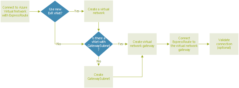
In this section we need to defined whether to use an existing or new ExpressRoute virtual network gateway and follow this decision tree for your AVS to Azure Native Services configuration.

Diagram showing the workflow for connecting Azure Virtual Network to ExpressRoute in Azure VMware Solution.

For this blog post, I will create a new vNET and new ExpressRoute and attach that vNET to Azure VMware Solution, so first thing first, Deploy your Azure VMware Solution and once done, go ahead and create an Azure Virtual Network and Virtual Network Gateway

Create Azure virtual network
  • On the Virtual Network page, select Create to set up your virtual network for your private cloud.
  • On the Create Virtual Network page, enter the details for your virtual network.
  • On the Basics tab, enter a name for the virtual network, select the appropriate region, and select Next
  • IP Addresses. (NOTE:-You must use an address space that does not overlap with the address space you used when you created your private cloud), Select + Add subnet, and on the Add subnet page, give the subnet a name and appropriate address range. When complete, select Add.
  • Select Review + create.
create AN virtual network gateway

Now that we have created a virtual network, we will now create a virtual network gateway.On the Virtual Network gateway page, select Create. On the Basics tab of the Create virtual network gateway page, provide values for the fields, and then select Review + create.

SubscriptionPre-populated value with the Subscription to which the resource group belongs.
Resource groupPre-populated value for the current resource group. Value should be the resource group you created in a previous test.
NameEnter a unique name for the virtual network gateway.
RegionSelect the geographical location of the virtual network gateway as AVS
Gateway typeSelect ExpressRoute.
SKULeave the default value: standard.
Virtual networkSelect the virtual network you created previously. If you don’t see the virtual network, make sure the gateway’s region matches the region of your virtual network.
Gateway subnet address rangeThis value is populated when you select the virtual network. Don’t change the default value.
Public IP addressSelect Create new.
Connect ExpressRoute to the virtual network gateway

Let’s go on the Azure portal, navigate to the Azure VMware Solution private cloud and select Manage > Connectivity > ExpressRoute and then select + Request an authorization key.

Provide a name for it and select Create. It may take about 30 seconds to create the key. Once created, the new key appears in the list of authorization keys for the private cloud.

Copy the authorization key and ExpressRoute ID. we will need them to complete the peering, now navigate to the virtual network gateway and select Connections > + Add

On the Add connection page, provide values for the fields, and select OK.

FieldValue
NameEnter a name for the connection.
Connection typeSelect ExpressRoute.
Redeem authorizationEnsure this box is selected
Virtual network gatewayThe virtual network gateway that we deployed above
Authorization keyPaste the authorization key copied in previous step
Peer circuit URIPaste the ExpressRoute ID copied in previous step

The connection between your ExpressRoute circuit and your Virtual Network is created successfully.

To test connectivity,I have deployed a VM on Azure VMware Solution and one VM in Native Azure and I can reach to both the VMs. I took console of AVS VM and can RDP to Azure Native VM and ping from Azure Native VM to VM deployed in AVS, this ensures that now we have successfully established connectivity between AVS and Azure Native.

Step -03 Create Storage and File Shares

Now lets move to Step -03, Azure file shares are deployed into storage accounts, which are top-level objects that represent a shared pool of storage. This pool of storage can be used to deploy multiple file shares.

Once you are on Azure portal, Click on “Create” under Storage account and create an storage account in the same region where we have Azure VMware Solution deployed. We will use this storage account to configure “Azure Files” over private link.

Once Storage Account is created, Lets get in to the networking section of storage account, which allows you to configure networking options. In addition to the default public endpoint for a storage account, Azure Files provides the option to have one or more private endpoints.

A private endpoint is an endpoint that is only accessible within an Azure virtual network and by AVS Network. When you create a private endpoint for your storage account, your storage account gets a private IP address from within the address space of your virtual network, much like how an on-premises file server or NAS device receives an IP address within the dedicated address space of your on-premises network.

Let’s create a “Private EndPoint by clicking on “+ Private endpoint”

Enter basic information as well choose “Region” should be in same region where your AVS has been deployed.

On the Next screen ensure to choose “Target sub-resource” – “file”

Select Azure Virtual Network and subnet that we created in step -02 and click on create

Once in the storage account, select the File shares and click on “+ File share”. The new file share blade should appear on the screen. Complete the fields in the new file share blade to create a file share:

  • Name: the name of the file share to be created.
  • Quota: the quota of the file share for standard file shares; the provisioned size of the file share for premium file shares.
  • Tiers: the selected tier for a file share. 

Now share is created, to Mount this share, Select File shares, which we need to mount and then click on “Connect

Select the drive letter to mount the share to ,choose Authentication method and Copy the provided script.

Step -04 Access Files over SMB

On the windows server which is running on Azure VMware Solution, Paste the script into a shell on the host you’d like to mount the file share to, and run it.

This should mount the “Azure File” to your windows server as Z: drive, which you can use to transfer/store any data that you want to transfer/store.

In case if you are facing issue while accessing file share using Host DNS Name, take private IP of the share connection by clicking on “Network Interface” and copy the private IP

Add this private IP Address in to windows servers Hosts file, then it should work as expected.

This completes integration of Azure VMware Solution to Azure Files (which is azure native service) over the private link, similarly Customers can use many more services of Azure Native those can be easily integrated with Azure VMware Solution.

Windows Bare Metal Servers on NSX-T overlay Networks

Featured

In this post, I will configure Windows 2016/2019 bare metal server as an transport node in NSX-T and then also will configure a NSX-T overlay segment on a Windows 2016/2019 server bare metal server, which allow VM and bare metal server on the same network to communicate.

To use NSX-T Data Center on a windows physical server (Bare Metal server), let’s first understand few terminologies which we will use in this post.

  • Application – represents the actual application running on the physical server server, such as a web server or a data base server.
  • Application Interface – represents the network interface card (NIC) which the application uses for sending and receiving traffic. One application interface per physical server server is supported.
  • Management Interface – represents the NIC which manages the physical server server.
  • VIF – the peer of the application interface which is attached to the logical switch. This is similar to a VM vNIC.

Now lets configure our windows server to operate in NSX overlay environment:

Enable WinRM service on Windows 2019

First of all we need to enable Windows Remote Management (WinRM) on Windows Server 2016/2019 to allow the Windows server to interoperate with third-party software and hardware. To enable the WinRM service with a self-signed certificate, Run:

[Net.ServicePointManager]::SecurityProtocol = [Net.SecurityProtocolType]::Tls12
PS$ wget -o ConfigureWinRMService.ps1 https://raw.github.com/vmware/bare-metal-server-integration-with-nsxt/blob/master/bms-ansible-nsx/windows/ConfigureWinRMService.ps1
PS$ powershell.exe -ExecutionPolicy ByPass -File ConfigureWinRMService.ps1.

Run the following command to verify the configuration of WinRM listeners:

winrm e winrm/config/listener

NOTE- For production bare metal servers, please enable winrm with HTTPS for security reasons and procedure is explained here

Installing NSX-T Kernel Module on Windows 2019 Server

Now let’s proceed with installing the NSX kernel module on the Windows Server 2016/2019 bare metal server. Make sure to download NSX kernel module for Windows server 2016/2019 with the same version of your NSX-T instance from VMware downloads

Start the installation of the NSX kernel module by executing the .exe file on your Windows BM server.

Configure the bare metal server as a transport node in NSX-T

Before we add the bare metal server as a transport node, we must need to create a new uplink profile in NSX-T that we are going to use for the bare metal servers. An uplink profile defines policies for the uplinks. The settings defined by uplink profiles can include teaming policies, active and standby links, transport VLAN ID, and MTU setting.

In my Lab the windows 2016/2019 bare metal server will have two network adapters, one NIC in the management VLAN and the other one is on a TEP VLAN (VLAN160).

once uplink profile is configured, We can now proceed with adding the Windows 2016/2019 bare metal server as transport node into NSX-T. In the NSX-T web page go to System –> Fabric –> Nodes and click on +ADD

Enter Management Interface IP address of your windows bare metal host and its credential, and do not change the Installation Location, it will validate your credentials against windows BM and then will allow you to move next

On the next screen, choose virtual switch name or leave it default, select overlay transport zone as we are connecting this to overlay and select uplink profile and management uplink interface.

on the next screen, configure IP address, Subnet and GW for TEP interface, this could be using specifying static IP list or choosing an IP pool which belongs to TEP VLAN.

Click on Next , This will start preparing your Winodws BM for NSX-T

​Once preparation/config completed, we can attach segment from above screen or we can Continue Later, lets click on “Continue Later” for now, we will add in different step.

Now if you see your windows BM in NSX-T console, it is ready for NSX-T and asking us to attach an overlay segment.

Attach Overlay Segement

Select host in the “Host Transport Nodes” section and click on “Action” and then click on “Manage Segment” which takes you to same screen that SELECT SEGMENT would have during original deployment

now select which segment the Application Interface for the Physical Server will reside on and click on “ADD SEGMENT PORT”

​Add Segment Port and Attach Application Interface

On the add Segment port screen:

Choose Assign New IP (This will be your application IP on Windows BM) – > NSX Interface Name (Default is “nsx-eth”) – This is Application Interface Name on Physical Server

Default Gateway –> Provide – T0 or T1 Gateway address

IP Assignment – i am doing Static, but you can also do DHCP or IP Pool for application interface.

Save –Once save is pressed, configuration is sent to Physical Server and you can see on physical server that Application IP has been assigned to an virtual interface.

Now you can see host config in NSX-T Manager console, everything is green and showing up.

Now if you see you can reach to this Bare Metal from a VM with IP address “172.16.20.101” which is on the same segment as this physical server without doing bridging.

if you click on windows server , you can see other information and specifically the “Geneve Tunnels” between ESXi host on which VM is running and Windows BM host on which your application is running.

This completes the configuration, this gives customers/partners an opportunity to run VM and Bare Metal servers on same network and security (like micro-segmentation) can be managed from single console that is NSX-T console. i hope this helps. please share your feedback 🙂

Cloud Native Runtimes for Tanzu

Featured

Dynamic Infrastructure

This is an IT concept whereby underlying hardware and software can respond dynamically and more efficiently to changing levels of demand. Modern Cloud Infrastrastructure built on VM and Containers requires automated:

  • Provisioning, Orchestration, Scheduling
  • Service Configuration, Discovery and Registry
  • Network Automation, Segmentation, Traffic Shaping and Observability

What is Cloud Native Runtimes for Tanzu ?

Cloud Native Runtimes for VMware Tanzu is a Kubernetes-based platform to deploy and manage modern Serverless workloads. Cloud Native Runtimes for Tanzu is based on Knative, and runs on a single Kubernetes cluster. Cloud Native Runtime automates all the aspects of dynamic Infrastructure requirements.

Serverless ≠ FaaS

ServerlessFaaS
Multi-Threaded (Server)Cloud Provider Specific
Cloud Provider AgnosticSingle Threaded Functions
Long lived (days)Shortly Lived (minutes)
offer more flexibilityManaging a large number of functions can be tricky

Cloud Native Runtime Installation

Command line Tools Required For Cloud Native Runtime of Tanzu

The following command line tools are required to be downloaded and installed on a client workstation from which you will connect and manage Tanzu Kubernetes cluster and Tanzu Serverless.

kubectl (Version 1.18 or newer)

  • Using a browser, navigate to the Kubernetes CLI Tools (available in vCenter Namespace) download URL for your environment.
  • Select the operating system and download the vsphere-plugin.zip file.
  • Extract the contents of the ZIP file to a working directory.The vsphere-plugin.zip package contains two executable files: kubectl and vSphere Plugin for kubectl. kubectl is the standard Kubernetes CLI. kubectl-vsphere is the vSphere Plugin for kubectl to help you authenticate with the Supervisor Cluster and Tanzu Kubernetes clusters using your vCenter Single Sign-On credentials.
  • Add the location of both executables to your system’s PATH variable.

kapp (Version 0.34.0 or newer)

kapp is a lightweight application-centric tool for deploying resources on Kubernetes. Being both explicit and application-centric it provides an easier way to deploy and view all resources created together regardless of what namespace they’re in. Download and Install as below:

ytt (Version 0.30.0 or newer)

ytt is a templating tool that understands YAML structure. Download, Rename and Install as below:

kbld (Version 0.28.0 or newer)

Orchestrates image builds (delegates to tools like Docker, pack, kubectl-buildkit) and registry pushes, works with local Docker daemon and remote registries, for development and production cases

kn

The Knative client kn is your door to the Knative world. It allows you to create Knative resources interactively from the command line or from within scripts. Download, Rename and Install as below:

Download Cloud Native Runtimes for Tanzu (Beta)

To install Cloud Native Runtimes for Tanzu, you must first download the installation package from VMware Tanzu Network:

  1. Log into VMware Tanzu Network.
  2. Navigate to the Cloud Native Runtimes for Tanzu release page.
  3. Download the serverless.tgz archive and release.lock
  4. Create a directory named tanzu-serverless.
  5. Extract the contents of serverless.tgz into your tanzu-serverless directory:
#tar xvf serverless.tar.gz

Install Cloud Native Runtimes for Tanzu on Tanzu Kubernetes Grid Cluster

For this installation i am using a TKG cluster deployed on vSphere7 with Tanzu.To install Cloud Native Runtimes for Tanzu on Tanzu Kubernetes Grid: First target the cluster you want to use and verify that you are targeting the correct Kubernetes cluster by running:

#kubectl cluster-info

Run the installation script from the tanzu-serverless directory and wait for progress to get over

#./bin/install-serverless.sh

During my installation, I faced couple of issues like this..

i just rerun the installation, which automatically fixed these issues..

Verify Installation

To verify that your serving installation was successful, create an example Knative service. For information about Knative example services, see Hello World – Go in the Knative documentation. let’s deploy a sample web application using the kn cli. Run:

#kn service create hello --image gcr.io/knative-samples/helloworld-go - default

Take above external URL and either add Contour IP with host name in local hosts file or add an DNS entry and browse and if everything is done correctly your first application is running sucessfully.

You can list and describe the service by running command:

#kn service list -A
#kn service describe hello -n default

It looks like everything is up and ready as we configured it. Some other things you can do with the Knative CLI are to describe and list the routes with the app:

#kn route describe hello -n default

Create your own app

This demo used an existing Knative example, why not make our own app from an image, let do it using below yaml:

apiVersion: serving.knative.dev/v1
kind: Service
metadata:
  name: helloworld
  namespace: default
spec:
 template:
  spec:
   containers:
     - image: gcr.io/knative-samples/helloworld-go
       ports:
             - containerPort: 8080
       env:
        - name: TARGET
          value: "This is my app"

Save this to k2.yaml or something which you like, now lets deploy this new service using the kubectl apply command:

#kubectl apply -f k2.yaml

Next, we can list service and describe new deployment, as per the name provided in the YAML file:

and now finally browse the URL by going to http://helloworld.default.example.com (you would need to add entry in DNS or hosts files)

This proves your application is running successfully, Cloud Native Runtimes for Tanzu is a great way for developers to move quickly go on serverless development with networking, autoscaling (even to zero), and revision tracking etc that allow users to see changes in apps immediately. GO ahead and try this in your Lab and once GA in production.

Quick Tip – Delete Stale Entries on Cloud Director CSE

Featured

Container Service Extension (CSE) is a VMware vCloud Director (VCD) extension that helps tenants create and work with Kubernetes clusters.CSE brings Kubernetes as a Service to VCD, by creating customized VM templates (Kubernetes templates) and enabling tenant users to deploy fully functional Kubernetes clusters as self-contained vApps.

Due to any reason, if tenant’s cluster creation stuck and it continue to show “CREATE:IN_PROGRESS” or “Creating” for many hours, it means that the cluster creation has failed for unknown reason, and the representing defined entity has not transitioned to the ERROR state .

Solution

To fix this, provider admin need to get in to API and delete these stale entries, there are very few simple steps to clean those stale entries.

First – Let’s get the “X-VMWARE-VCLOUD-ACCESS-TOKEN” for API calls by calling below API call:

  • https://<vcd url>/cloudapi/1.0.0/sessions/provider
  • Authentication Type: Basic
  • Username/password – <adminid@system>/<password>

Above API call will return “X-VMWARE-VCLOUD-ACCESS-TOKEN”, inside header section of response window. copy this token and use as “Bearer” token in subsequent API calls.

Second – we need to get the “Cluster ID” of the stale cluster which we want to delete, and to get “Cluster ID” – Go in to Cloud Director Kubernetes Container Extension and click on cluster which is stuck and get Cluster IP in URN Format.

Third (Optional) – Get the cluster details using below API call and using authentication using Bearer token , which we first step:

Get  https://<vcd-fqdn>/cloudapi/1.0.0/entities/<cluster-id>/

Fourth – Delete the stale cluster using below API call by providing “ClusterID“, which we captured in second step and using authenticate type a “Bearer Token

Delete https://<vcd-fqdn>/cloudapi/1.0.0/entities/<cluster-id>/

Above API call should respond with “204 No Content”, it means API call has been executed sucessfully.

Now if you login to Cloud Director “Kubernetes Container Cluster” extension, above API call must have deleted the stale/stuck cluster entry

Now you can go to Cloud Director vAPP section and see if any vAPP/VM is running for that cluster , shutdown that VM and Delete it from Cloud Director. simple three API calls to complete the process.

VMware Cloud Director Assignable Storage Policies to Entity Types

Featured

Service providers can use storage policies in VMware Cloud Director to create a tiered storage offering like: Gold, Silver and Bronze or even offer dedicated storage to tenants. With the enhancement of storage policies to support VMware Cloud Director entities, Now providers has the flexibility to control how tenant use the storage policies. Providers can have not only tiered storage, but isolated storage for running VMs, containers, edge gateways, Catalog and so on.
A common use case that this Cloud Director 10.2.2 update addresses is the need for shared storage across clusters or offering lower cost storage for non-running workloads. For example, instead of having a storage policy with all VMware Cloud Director entities, you can break your storage policy into a “Workload Storage Policy” for all your running VMs and containers, and dedicate a “Catalog Storage Policy” for longer term storage. A slower or low cost NFS option can back the “Catalog Storage Policy”, while the “Workload Storage Policy”  can run on vSAN.

Starting with VMware Cloud Director 10.2.2, if Provider do not want a provider VDC storage policy to support certain types of VMware Cloud Director entities, you can edit and limit the list of entities associated with the policy, here is the list of supported entity types:

  • Virtual Machines – Used for VMs and vApps and their disks
  • VApp/VM Templates – Used for vApp Templates
  • Catalog Media – Used for Media inside catalogs
  • Named Disks – Used for Named disks
  • TKC – Used for TKG Clusters
  • Edge Gateways – Used for Edge Gateways

You can limit the entity types that a storage policy supports to one or more types from this list. When you create an entity, only the storage policies that support its type are available.

Use Case – Catalog-Only Storage Policy

There are many use cases of using assignable storage policies, i am demonstrating this one because many of providers has asked this feature in my discussions. so for this use case we will take entity type – Media, VApp Template

Adding Media, VApp Template entity types to a storage policy marks a storage policy as being able to be used with VDC catalogs.These entity types can be added at the PVDC storage policy layer. Storage policies that are associated with datastores that are intended for catalog-only storage can be marked with these entity types, to force only catalog-related items in to catalog only storage datastore.

When added: VCD users will be able to use this storage policy with Media/Templates. In other words, tenants will see this storage policy as an option when pre-provisioning their catalogs on a specific storage policy.

  • In Cloud Director provider portal, select Resources and click Cloud Resources.
  • select Provider VDCs, and click the name of the target provider virtual data center.
  • Under Policies, select Storage
  • Click the radio button next to the target storage policy, and click Edit Supported Types.
  • From the Supports Entity Types drop-down menu, select Select Specific Entities.
  • Select the entities that you want the storage policy to support, and click Save.

Validation

Lets validate this functionality by login as a tenant and go into “Storage Policies” settings and here we can see this Org VDC has two storage Policy assigned by provider.

Now lets deploy a virtual machine in the same org VDC and you can see that policy “WCP” which was marked as catalog only is not available for VM provisioning.

In the same Org VDC lets create a new “Catalog”, here you can see both the policies are visible, one exclusively for “Catalog” and another one which is allowed for all entity types.

Policy Removal: VCD users will not be able to use this storage policy with Media/Templates but whatever is there will continue to be there.

This addition to Cloud Director gives opportunity to providers to manage storage based on entity type , This is the one use case similarly one particular storage can be used for Edge Placement , another one could be used to spin up production grade Tanzu Kubernetes Cluster while default storage can be used by CSE native Kubernetes cluster for development container workloads. This opens up new Monetization opportunities for provider, upgrade your Cloud Director environment and start monetizing.

This Post is also available as Podcast

Auto Scale Applications with VMware Cloud Director

Featured

Starting with VMware Cloud Director 10.2.2, Tenants can auto scale applications depending on the current CPU and memory utilization. Depending on predefined criteria for the CPU and memory use, VMware Cloud Director can automatically scale up or down the number of VMs in a selected scale group.

Cloud Director Scale Groups are a new top level object that tenants can use to implement automated horizontal scale-in and scale-out events on a group of workloads. You can configure auto scale groups with:

  • A source vApp template
  • A load balancer network
  • A set of rules for growing or shrinking the group based on the CPU and memory use

VMware Cloud Director automatically spins up or shuts down VMs in a scaling group based on above three settings.This blog post will help you to enable Scale Goups in Cloud Director and also we will configure Scale Groups.

Configure Auto Scale

Login to Cloud Director 10.2.2 cell with admin/root credential and eanble metric data collection and publishing by setting up the metrics collection in a Cassandra database or collect metrics without metrics data persistence. in this post we are going to configure without metrics data persistence, to collect metrics data without data persistence, run the following commands:

#/opt/vmware/vcloud-director/bin/cell-management-tool manage-config -n statsFeeder.metrics.collect.only -v true 

#/opt/vmware/vcloud-director/bin/cell-management-tool manage-config -n statsFeeder.metrics.publishing.enabled -v true

Now the second step is to create a file named “metrics.groovy” file in the /tmp folder of cloud director appliance with the following contents:

configuration {
    metric("cpu.ready.summation") {
        currentInterval=20
        historicInterval=20
        entity="VM"
        instance=""
        minReportingInterval=300
        aggregator="AVERAGE"
    }
}

Change the file permission appropriatly and import the file using below command:

$VCLOUD_HOME/bin/cell-management-tool configure-metrics --metrics-config /tmp/metrics.groovy

Lets enable auto scalling plugin by running below commands on Cloud Director Cell:

$VCLOUD_HOME/bin/cell-management-tool configure-autoscale --set enabled=true
$VCLOUD_HOME/bin/cell-management-tool configure-autoscale --set username=<username> (should having admin priveldge account)
$VCLOUD_HOME/bin/cell-management-tool configure-autoscale --encrypt --set password=<password> ( Password for the above account)

If you see in the Cloud Director provider console, under customize portal , there will be a plugin which provider can enable to tenants who needs auto scale functionality for the applications or can be made available to all tenants.

Since Auto Scale released with VMware Cloud Director 10.2.2, which allows service providers to grant tenant rights to create scale groups.Under Tenant Access Control, select Rights Bundles and then select the “vmware:scalegroup Entitlement” bundle, and click Publish.

Also ensure provider Add the necessary VMWARE:SCALEGROUP rights to the tenant roles that want to use scale groups.

Tenant Self Serive

On the Tenant portal after login, select Applications and select the Scale Groups tab and Click New Scale Group.

Select an organization VDC in which tenant want to create the scale group.

Or Tenant can also access scale groups from a selected organization virtual data center (VDC) by going in to specific organization VDC

  • Enter a name and a description of the new scale group.
  • Select the minimum and maximum number of VMs to which you want the group to scale and click Next.

Select a VM template for the VMs in the scale group and a storage policy, and click Next. Template needs to be pre-populated in catalog by tenant or can be by provider and published for tenants.

Next step is to select a network for the scale group.If Tenants oVDC is backed by NSX-T Data Center and NSX ALB (AVI) has been published as a load balancer by provider, then tenant can choose NSX ALB load Balancer edge on which load balacing has been enabled and Server pool has been setup by tenant before enabling Scale Groups.

If tenant want to manage the load balancer on your own or if there is no need for a load balancer, thenn select I have a fully set-up network, Auto Scale will automatically adds VM to this network.

VMware Cloud Director starts the initial expansion of the scale group to reach the minimum number of VMs, besically it will start creating a VM from template that tenant selected while creating scale group and it will continue to spin up to minimum number VM spacified in the scale group section.

Add an Auto Scaling Rule

  1. Click Add Rule.
  2. Enter a name for the rule.
  3. Select whether the scale group must expand or shrink when the rule takes effect.
  4. Select the number of VMs by which you want the group to expand or shrink when the rule takes effect.
  5. Enter a cooldown period in minutes after each auto scale in the group.The conditions cannot trigger another scaling until the cooldown period expires and cooldown period resets when any of the rules of the scale group takes effect.
  6. Add a condition that triggers the rule.The duration period is the time for which the condition must be valid to trigger the rule. To trigger the rule, all conditions must be met.
  7. To add another condition, click Add Condition. tenant can add multiple conditions.
  8. Click Add.

From the details view of a scale group, when you select Monitor, you can see all tasks related to this scale group. For example, you can see the time of creation of the scale group, all growing or shrinking tasks for the group, the rules that initiated the tasks, in side Virtual Machine section which VM has been created at what time and what is the IP address of the VM etc…

here is the section showing scale takes which trigered and its status.

Virtual Machine section as said provides scale group VM information anf its details.

here is the another section showing scale takes which trigered and thier status , start time and completion time.

Auto Scale Group in Cloud Director 10.2.2 brings very important functionality nativily to cloud director which does not require any external configuration like vRealize Orchestrator or vRops and does not incure addional cost to tenant or provider. go ahead uprade your cloud director , enable it and let the tenant enjoy this cool functionality.

vSphere Tanzu with AVI Load Balancer

Featured

With the release of the vSphere 7.0 Update 2, VMware now adds new Load Balancer option for vSphere with Tanzu which provides production-ready load balancer option for your vSphere with Tanzu deployments. This Load Balancer is called NSX Advanced Load Balancer, or NSX ALB or AVI Load Balancer, This will provide Virtual IP addresses for the Supervisor Control Plane API server, the TKG guest cluster API servers and any Kubernetes applications that require a service of type Load Balancer. In this post, I will go through a step-by-step deployment of the new NSX ALB along with vSphere with Tanzu.

VLAN & IP address Planning

There are many way to plan IP, in this Lab I will place management ,VIPs and workload nodes on three different networks. For this deployment , I will be using three VLANs, One for Tanzu Management, One for Frontend or VIP and one for Supervisor cluster and TKG clusters , here is my IP Planning sheet:

Deploying & Configuring NSX ALB (AVI)

Now Lets deploy NSX ALB controller (AVI LB) by following very similar process that we follow to deploy any other OVA and I will be assigning NSX ALB IP management address from management network address range. The NSX ALB is available as an OVA. In this deployment, I am using version 20.1.4.The only information required at deployment time are

  • A static IP Address
  • A subnet mask
  • A default gateway
  • An sysadmin login authentication key

I have deployed one controller appliance for this Lab but if you are doing production deployment , it is recommended to create three node controller cluster for high availability and better performance.

Once OVA deployment completes, power on the VM and wait for some time before you browse NSX ALB url using the IP address provided while deployment and login to Controller and then:

  • Enter DNS Server Details and Backup Passphrase
  • Add NTP Server IP address
  • Provide Email/SMTP details ( not mandatory)

Next Choose VMware vCenter as your “Orchestrator Integration”, This creates a new cloud configuration in the NSX ALB called as Default-Cloud. Enter below details on next screen:

  • Insert IP of your vCenter,
  • vCenter Credential
  • Permission – Write Permission
  • SDN Integration – None
  • Select appropriate vCenter “Data Center”
  • For Default Network IP Address Management – Static

On next screen, we define the IP address pool for the Service Engines.

  • Select Management Network (on this Network “management interface” of “service engine” will get connected)
  • Enter IP Subnet
  • Enter Free IP’s in to IP Address Pool section
  • Enter Default Gateway

Select No for configuring multiple Tenants. Now we’re ready to get into the NSX ALB configuration.

Create IPAM Profile

IPAM will be used to assign VIPs to Virtual Services, Kubernetes control planes and applications running inside pods. to create IPAM Go to: Templates -> Profiles -> IPAM/DNS Profiles

  • Assign Name to the Profile , This IPAM will be for “frontend” Network
  • Select Type – “Avi Vantage IPAM
  • Cloud for Usable Network – Choose “Default-Cloud
  • Usable Network – Choose Port group, in my case “frontend” ( all vCenter port groups will get populated automatically by vCenter discovery)

Create and Configure DNS profile as below: ( This is optional)

Go to “Infrastructure” and click on “Cloud” and edit “Default Cloud” and update IPAM Profile and DNS profiles with the IPAM profile and DNS profile that we created above.

 Configure the VIP Network

On NSX ALB console , go to “Infrastructure” and then “Networks” , this will display all the network discovered by NSX ALB. Select “frontend” network and Click on Edit

  • Click on “Add Subnet
  • Enter subnet , in my case – 192.168.117.0/24
  • Click on Static IP Address pool:
  • Ensure “Use Static IP Address for VIPs and SE” is selected
    • and enter IP Segment Pool , in my case 192.168.117.100-192.168.117.200
    • Click on Save

Create New Controller Certificate

Default AVI certificate doesn’t contain IP SAN and can’t be used by vCenter/Tanzu to connect to AVI, so we need to create a custom controller and use it during Tanzu management plane deployment. let’s create controller certificate by going to Templates -> Security -> SSL/TLS Certificates -> Create -> Controller Certificate

Complete the Page with required information and make sure “Subject Alernative Name (SAN)” is NSX ALB controller IP/Cluster IP or hostname.

Then go to Administration -> Settings -> Access Settings and edit System Access Settings:

Delete all the certificates in SSL/TLS certificate filed and choose the certificate that we created in above section.

Go to Template->Security->SSL/TLS Certificates, Copy the certificate we created to use while enabling Tanzu Management plane

Configure Routing

Since the workload network (192.168.116.0/24) is on a different subnet from the VIP network (192.168.170.0/24), we need to add a static route in NSX ALB controller, Go the Infrastructure page, navigate to Routing and then to Static Route. Click the Create button and create static routes accordingly.

Enable Tanzu Control Plane (Workload Management)

I am not going to go through the full deployment of workload management, these are similar steps detailed HERE . However, there are a few steps that are different:

  • On page 6 Choose Type=AVI as your Load Balancer type.
  • there is no load balancer IP Address range required, this is now provided by the NSX ALB.
  • the Certificate we need to provide, should be of NSX ALB which we created in previous step.

The new NSX Advanced Load Balancer is far superior to the HA-Proxy specially in provider environment. The providers can deploy, offer and manage K8 clusters with VMware supported LB type even though the configuration requires a few additional steps, it is very simple to setup. The visibility provided into health and usage of the virtual services are going to be extremely beneficial for day-2 operations, and should provide great insights for those providers who are responsible for provisioning and managing Kubernetes distributions running on vSphere. Feel free to share any feedback…

Deploy Cloud Director orgVDC Edge API Way

Recently working with a provider who was needed some guidance on deploying orgVDC Edge API way so that their developer can use API way to automate customer orgVDC edge deployment for tenants. so here are are steps which i shared with him , sharing here too..lets get started..

First thing is we need to authenticate to Cloud Director, in this example, my credentials is the equivalent of cloud director System Administrator and I am connecting to provider session using Open API cloud director API and choose Authorization as basic with provider credential.

let’s do the post API call for getting an API session token.

POST - https://<vcdurl>/cloudapi/1.0.0/sessions/provider

Once you have authenticated, click on the Headers tab and you will see your Authorization key for this session. the Key “X-VMWARE-VCLOUD-ACCESS-TOKEN”, we will use this key to authenticate further API sessions using “Bearer” token

Next API Call is to get the current Edge gateways deployed by using above “Bearer Token”. this for me was the easiest way to reference required objects for next API call. (i deployed a sample edge in Org to get references)

Result of above API call , will give you lots of information that will be used in our next API call to create an Edge:

Now Lets create orgVDC edge by creating body for POST API Call, From above result take few mandatory filed values like:

  • uplinkID
  • Subnets/gateway/IP address will be as per your environment
  • orgVDC and Its ID
  • OwnerRef , name and its id
  • OrgRef, name and its id

Here is reference payload of my API call for orgVDCEdge creation

{
            "name": "avnish2",
            "description": "test avnish2",
            "edgeGatewayUplinks": [
                {
                    "uplinkId": "urn:vcloud:network:e0d2cd31-3034-489c-b318-cd36efe89729",
                    "subnets": {
                        "values": [
                            {
                                "gateway": "172.16.43.1",
                                "prefixLength": 24,
                                "ipRanges": {
                                    "values": [
                                        {
                                          "startAddress": "172.16.43.41",
                                          "endAddress": "172.16.43.50"
                                        }
                                    ]
                                },
                                "enabled": true,
                                "primaryIp": "172.16.43.2"
                            }
                        ]
                    },
                    "connected": true,
                    "quickAddAllocatedIpCount": null,
                    "dedicated": false,
                    "vrfLiteBacked": false
                }
            ],
            "orgVdc": {
                "name": "avnish-ovdc",
                "id": "urn:vcloud:vdc:45202398-51ee-4887-886a-1eecb9fdaa1c"
            },
            "ownerRef": {
                "name": "avnish-ovdc",
                "id": "urn:vcloud:vdc:45202398-51ee-4887-886a-1eecb9fdaa1c"
            },
            "orgRef": {
                "name": "Avnish",
                "id": "urn:vcloud:org:ddf6d02f-1552-49ac-8c25-30c36f63d5b6"
            }

        }

Do the Post to https://<vcdip>/cloudapi/1.0.0/edgeGateways

you should see “accepted” response , which confirms that Cloud Director will deploy OrgVDC edge with the information that you provided in the above post API call.

Once you got “accepted” response , if you go to Cloud Director , you should see above call should have deployed “OrgVDC Edge” for a specific organisation.

I hope this helps in case if you want to use API way to provision orgVDC Edge for a tenant.

SSL VPN with Cloud Director

Secure remote access to the cloud services is essential to cloud adoption and use. Cloud Director based cloud allows every tenant to use a dedicated edge gateway, providing a simple and easy-to-use solution that supports IPsec site-to-site virtual private networks (VPNs) backed by VMware NSX-T. Since NSX-T today does not support SSL VPN and this limitation requires providers or tenants to select alternative solutions, including open source or commercial, depending on the desired mix of features and support. Example of such solutions are OpenVPN or Wireguard.

In this blog post we will deploy openVPN as a tenant admin to allow access cloud resources from Cloud using VPN Client.

Create a new VDC network

Lets create a new routed Org VDC Network and we will deploy OpenVPN on this network, you can also deploy it on existing routed network.

  1. In Cloud Director go to Networking Section and Click on New to create a new router Network
  2. Select the appropriate Org VDC
  3. Select Type of Network as “Routed”
  4. Choose appropriate Edge for this routed network association
  5. Give the network an Gateway CIDR
  6. Create a pool of IPs for Network to allocate
  7. check the summary and click finish to create a network a routed netwrok

Creating NAT Rules

After creating routed network, go on to Edge gateway and open the edge gateway configuration:

Create two NAT rules for OpenVPN appliance:

  1. SNAT rule to allow OpenVPN appliance out bound Internet access
    1. OpenVPN Appliance IP to one External IP
  2. DNAT rule to allow OpenVPN appliance Inbound access from Internet
    1. External IP to OpenVPN appliance IP

You might have to open certain firewall rules to access OpenVPN admin console which depend on from where you are accessing the console.

NAT for Cloud Director Services

Since Cloud Director Service is managed service and its architecture is different then cloud providers environment, so for CDS, we need to follow few extra steps as explained below:

Deploy OpenVPN Appliance

  1. I have downloaded the latest OpenVPN appliance from Here: -https://openvpn.net/downloads/openvpn-as-latest-vmware.ova
  2. I have uploaded in to a catalog , Select from Catalog and Click on Create vAPP

Provide a Name and Description

Select the Org VDC

Edit VM configuration

This is very important step , make sure you choose:

  1. Switch to the advance networking workflow
  2. Change IP assignment to “Manual
  3. assign a valid IP Manually from the range which we had created during network creation, if you are not putting IP here then on appliance you need to struggle for IP assignment etc..

Review and finish, This will deploy the OpenVPN appliance, once deployed power on the appliance. Now time to configure the appliance…

OpenVPN Initial Configuration

In VMware Cloud Director go to Compute and click on Virtual Machines and open the console of your OpenVPN virtual machine.

Log in to the VM as the root user and for Password – Click on “Guest OS Customization” and click on Edit

Copy the password which is in the section “Specify password“, and use this password to login to OpenVPN virtual machine

After login, you will be prompted to answer few questions:

Licence Agreement:  as usual , you do not have choice, Enter “yes”

Will this be the primary Access Server node?: Enter “Yes”

Please specify the network interface and IP address to be used by the Admin Web UI:  If the guest customizations were applied correctly, this should default to eth0, which should be configured with an IP address on the network you selected during deployment.

Please specify the port number for the Admin Web UI: Enter your desired port number, or accept the default of 943.

Please specify the TCP port number for the OpenVPN Daemon: Use default “443”

Should client traffic be routed by default through VPN?: Choose “No”.

if you enter “yes”, it will not allow client device from accessing any other networks while the VPN is connected.

Should client DNS traffic be routed by default through the VPN?: Choose “No” if your above answer is “No”.

Use local authentication via internal DB? : Enter Yes or No based on your choice of authentication.

Should private subnets be accessible to clients by default? : Enter “yes” this will enable your cloud networks accessible via the VPN.

Do you wish to login to the Admin UI as “openvpn”?: Answer “yes” which will create a local user account named as “openvpn” If you answer no, you’ll need to set up a different user name and password.

Please specify your Activation key: If you’ve purchased a licence, enter the licence key, otherwise leave this blank.

If using default “openvpn” account, after installing the OpenVPN Access Server for the first time, you are required to set a password for the “openvpn” user at the command line interface with the command “#passwd openvpn” and then use that to login at the Admin UI. This completes the deployment of appliances, now you can browse the config page, on which we will configure SSL VPN specific Options:

This section shows you whether the VPN Server is currently ON or OFF. Based on the current status, you can either Start the Server or Stop the Server with the button you see there.

Inside VPN Network settings , specify network settings which applies to your configuraiton.

Create users or configure Other authentication methods, i am creating a sample user to access cloud resources based on the permissions.

Tenant User Access

Tenant user access public IP of SSL VPN that we had assigned initially and login with credentials

Once Login , User has choice to download the VPN Client as well as Connection profiles , these connection profiles will have login information for the user.

Incase if user sees private IP in profile, (@192.168.10.101), then click on pen icon to edit the profile

Once user has edit the profile, he can successfully connect to Cloud.

While Label OpenVPN

In case provider wants to while label the OpenVPN, he can easily do this by following the simple procedure:

  1. Copy an Logo to OpenVPN appliance and edit file – nano /usr/local/openvpn_as/etc/as.conf
  2. Add below line after #sa.company_name line for company logo
    1. sa.logo_image_file=/usr/local/openvpn_as/companylogo.png
  3. uncomment sa.company_name and change it to your specific text desired for Company Name for changing company name
  4. To hide footer, below the sa.company_name and/or sa.logo_image_file variables, add the following:cs.footer=hide
  5. Save and exit the file, then restart the OpenVPN Access Server:service openvpnas restart

This completes the installation/configuration and white Labelling of the OpenVPN and these configure steps applies to VMware Cloud Director and Cloud Director service’s tenant portal on VMware Cloud on AWS, Please share feedback if any.

Tanzu Basic – Building TKG Cluster

Featured

In Continuation to our Tanzu Basic deployment series , this is the last part and by now we have our vSphere with Tanzu cluster enabled and deployed, now the next step would be to create Tanzu Kubernetes Clusters. In case if you missed previous posts , here they are:

  1. Getting Started with Tanzu Basic
  2. Tanzu Basic – Enable Workload Management

Create a new namespace

vSphere Namespaces is kind of a resource pool or a container that i can give to a project, team or customer a “Kubernetes+VM environment” where they can create and manage their application containers and virtual machines. They can’t see the other’s environment and they can’t expand past their limits set by Administrators. The vSphere Namespace construct allows the vSphere admin to set several policies in one place. The user/team/customer/project can create new workloads to their desire within their vSphere Namespace. You also set resources limits to the namespace and permissions so that DevOps engineers can access it. Let’s create our first name space by going to vCenter Menu and Click on “Workload Management”

Once you are in “Workload Management” place , click on “CREATE NAMESPACE”

Select the vSphere Cluster on which you enabled “workload management”

  1. Give DNS compliant name of the namespace
  2. Select Network for the namespace

Now we have successfully created “namespace” named “tenant1-namespace”

Next step is to Add Storage. here we need to choose a vCenter Storage policy which TKG will use to provisition control plane VMs as well as this policy will show up as a Kubernetes Storage Class for this namespace.The persistent volume claims that correspond to persistent volumes can originate from the Tanzu Kubernetes cluster.

After you assign the storage policy, vSphere with Tanzu creates a matching Kubernetes storage class in the Namespace. For the VMware Tanzu Kubernetes Clusters, the storage class is automatically replicated from the namespace to the Kubernetes cluster. When you assign multiple storage policies to the namespace, a separate storage class is created for each storage policy.

Access Namespace

Share the Kubernetes Control Plane URL with DevOps engineers as well as the user name they can use to log in to the namespace through the Kubernetes CLI Tools for vSphere. You can grant access to more than one namespace to a DevOps engineer.

Developer browse the URL and downloads TKG CLI plugin for their environment (Windows, Linux or MAC)

To provision Tanzu Kubernetes clusters by using the Tanzu Kubernetes Grid Service, we connect to the Supervisor Cluster by using the vSphere Plugin for kubectl which we downloaded from above step and authenticate with your vCenter Single Sign-On credentials, which was given by vSphere admin to developer.

After you log in to the Supervisor Cluster, the vSphere Plugin for kubectl generates the context for the cluster. In Kubernetes, a configuration context contains a cluster, a namespace, and a user. You can view the cluster context in the file .kube/config. This file is commonly called the kubeconfig file.

I am switching to “tenant1-namespace” context as i have access to multiple name spaces , similarly devops user can switch to context by following command.

Below commands to explore and help you to find out right VM type for Kubernetes Clusters sizing:

#kubectl get sc

This command will list down all the storage classes

#kubectl get virtualmachineimages

This command will list down all the VM images available for creating TKG clusters, this will help you decide the Kubernetes version that you want to use

#kubectl get virtualmachineclasses

This command will list all the machine classes (T-Shirt sizes) available for TKG clusters

Deploy a TKG Cluster

To deploy a TKG cluster we need to create a YAML file with the required configuration parameters to define the cluster.

  1. Above YAML provisions a cluster with a three control plane nodes and three worker nodes.
  2. The apiVersion and kind parameter values are constants.
  3. The Kubernetes version, listed as v1.18, is resolved to the most recent distribution matching that minor version.
  4. The VM class best-effort-<size> has no reservations. For more information, see Virtual Machine Class Types for Tanzu Kubernetes Clusters.

Once file is ready, lets provision the Tanzu Kubernetes cluster using the following kubectl command:

Monitor cluster provisioning using the vSphere Client , TKG management plane creating Kubernetes cluster automatically

Verify cluster provisioning using the following kubectl commands.

you can continue to monitor/verify cluster provisioning using the #kubectl describe tanzukubernetescluster command, at the last of the command output , it shows:

Node Status – It shows nodes status from Kubernetes prospective

VM Status – It shows nodes status from vCenter prospective

After around 15/20 minutes, you should see VM & Node Status as ready and it will also show the Phase as Running.This completes deployment of Kubernetes cluster on vSphere7 with Tanzu and we successfully deployed a Kubernetes cluster, now lets deploy a application and expose to external world.

Deploy an Application

To deploy your first application we need to login to new cluster that we created , you can use below command”

#kubectl vsphere login --server=IP-ADDRESS --vsphere-username USERNAME --tanzu-kubernetes-cluster-name CLUSTER-NAME --tanzu-kubernetes-cluster-namespace NAMESPACE

Once login completed, we can deploy application workloads to Tanzu Kubernetes clusters using pods, services, persistent volumes, and higher-level resources such as Deployments and Replica Sets. lets deploy an application using below comand:

#kubectl run --restart=Never --image=gcr.io/kuar-demo/kuard-amd64:blue kuard

Command now has successfully deployed application, lets expose so that we can access it using VMware HA proxy Load Balancer:

#kubectl expose pod kuard --type=LoadBalancer --name=kuard --port=8080 

Application exposed successfully, lets get the public IP which has been assigned to application by the above command , so here is the external IP – 192.168.117.35

Let’s access the application using the IP assigned to application and see if we can easily access the application.

Get Visibility of Cluster using Octant

Octant is a tool for developers to understand how applications run on a Kubernetes cluster. It aims to be part of the developer’s toolkit for gaining insight and approaching complexity found in Kubernetes. Octant offers a combination of introspective tooling, cluster navigation, and object management along with a plugin system to further extend its capabilities.Installation is pretty simple and detailed Here

This completes the series with the installation of TKG Kubernetes cluster and run an application on top of it and accessing that application using HA proxy. !!Please share your feedback if any!!

Tanzu Basic – Enable Workload Management

Featured

In continuation to last post where we had deployed VMware HA proxy, now we will enable a vSphere cluster for Workload Management, by configuring it as a Supervisor Cluster.

Part-1- Getting Started with Tanzu Basic – Part1

What is Workload Management

With Workload Management we can deploy and operate the compute, networking, and storage infrastructure for vSphere with Kubernetes. vSphere with Kubernetes transforms vSphere to a platform for running Kubernetes workloads natively on the hypervisor layer. When enabled on a vSphere cluster, vSphere with Kubernetes provides the capability to run Kubernetes workloads directly on ESXi hosts and to create upstream Kubernetes clusters within dedicated resource pools

Since we selected creating a Supervisor Cluster with the vSphere networking stack in previous post that means vSphere Native Pods will not be available but we can create Tanzu Kubernetes clusters.

Pre-Requisite

As per our HA proxy deployment , we chosen HAProxy VM with three virtual NICs, thus connecting HAProxy to a Frontend network. DevOps users and external services can access HAProxy through virtual IPs on the Frontend network. Below are the pre-requisite to enable Workload Management

  • DRS and HA should be enabled on the vSphere cluster, and ensure DRS is in the fully automated mode.
  • Configure shared storage for the cluster. Shared storage is required for vSphere DRS, HA, and storing persistent volumes of containers.
  • Storage Policy: Create a storage policy for the placement of Kubernetes control plane VMs.
    • I have created policy two policies named “basic” & “TanzuBasic”
    • NOTE: You should created policy with lower case policy name
    • This policy has been created with Tag based placement rules
  • Content Library: Create a subscribed content library using URL: https://wp-content.vmware.com/v2/latest/lib.json on the vCenter Server to download VM image that is used for creating nodes of Tanzu Kubernetes clusters. The library will contain the latest distributions of Kubernetes.
  • Add all hosts from the cluster to a vSphere Distributed Switch and create port groups for Workload Networks

Deploy Workload Management

With the release of vSphere 7 update 1 a free trial of Tanzu is available for 60 day evaluation . Enter your details to receive communication from VMware and get started with Tanzu

 Next screen takes you to choose networking options available with vCenter, make sure

  • You choose correct vCenter
  • For networking there are two networking stack, since we haven’t installed NSX-T it will be greyed out and unavailable, choose “vCenter Server Network” and move to “Next”

On next screen you will be presented with vSphere Clusters which are compatible for Tanzu, incase you don’t see any cluster, go on to “Incompatible” section and click on cluster which will give you guidance for the reason of incompatible, go back and fix the reason and try again

Select the size of the resource allocation you need for the Control Plane. For the evaluation, Tiny or Small should be enough and click on Next.

Storage: Select the storage policy which we created as per of pre-requisite and click on Next

Load Balancer: This section is very important and we need to ensure that we provide correct values:

  • Enter a DNS-compliant, don’t use “under-score” in the name
  • Select the type of Load Balancer: “HA Proxy”
  • Enter the Management data plane IP Address. This is our management ip and port number assigned to VMware HA proxy management interface.In our case it is 192.168.115.10:5556.
  • Enter the username and password used during deployment for the HA Proxy
  • Enter the IP Address Ranges for Virtual Server. we need to provide the IP ranges for virtual servers, these are the ip-address which we had defined in the frontend network. It’s the exact same range which we used during deployment of HA-proxy configuration process, but this time we will have to write full range instead of using a CIDR format, in this case i am using: 192.168.117.33-192.168.117.62
  • Finally, enter in the Server CA cert. If you have added a cert during deployment, you would use that. If you have used a self-signed cert then you can retrieve that data from the VM by browsing /etc/haproxy/ca.crt.

Management Network: Next portion is to configure IP address for Tanzu supervisor control plane VM’s, this will be from management IP range.

  • We will need 5 consecutive IPs free from Management IP range, Starting IP Address this is the first IP in a range of five IPs to assign to Supervisor control plane VMs’ management network interfaces.
  • One IP is assigned to each of the three Supervisor control plane VMs in the cluster
  • One IP is used for a Floating IP which we will use to connect to Management plane
  • One IP is reserved for use during upgrade process
  • This will on mgmt port group

Workload Network:

Service IP Address: we can take the default network subnet for “IP Address for Services. change this if you are using this subnet anywhere else. This subnet is for internal communication and it not routed.

And the last network in which we will define the Kubernetes node IP range, this applies to both the supervisor cluster as well as the guest TKG clusters. This range will be from workload IP range which we had created in the last post with vLAN 116.

  • Port Group – workload
  • IP Address Range – 192.168.116.32-192.168.116.63

Finally choose the content library which we had created as a part of pre-requisite

if you have provided right information with correct configuration, it will take around 20 minutes to install and configure entire TKG management plane to consume. you might see few errors while configuring Management plane but you can ignore as those operations will be retried automatically and errors will get clear when that particular task get succeed.

NOTE-Above screenshot has different cluster name as i have taken it from different environment but IP schema is same.

I hope this article helps you to enable your first “Workload Management” vSphere cluster without NSX-T. Next Blog post i will cover deployment of TKG Clusters and others things around that…

Getting Started with Tanzu Basic

In the process of modernize your data center to run VMs and containers side by side, Run Kubernetes as part of vSphere with Tanzu Basic. Tanzu Basic embeds Kubernetes in to the vSphere control plane for the best administrative control and user experience. Provision clusters directly from vCenter and run containerized workloads with ease. Tanzu basic is the most affordable and has below components as part of Tanzu Basic:

To Install and configure Tanzu Basic without NSX-T, at high level there are four steps which we need to perform and I will be covering all the steps in three blog posts:

  1. vSphere7 with a cluster with HA and DRS enabled should have been already configured
  2. Installation of VMware HA Proxy Load Balancer – Part1
  3. Tanzu Basic – Enable Workload Management – Part2
  4. Tanzu Basic – Building TKG Cluster – Part3

Deploy VMware HAProxy

There are few topologies to setup Tanzu Basic with vSphere based networking, for this blog we will deploy the HAProxy VM with three virtual NICs, which means there will be one “Management” network , one “Workload” Network and another one will be “frontend” network which will be used by DevOps users and external services will also access HAProxy through virtual IPs on this Frontend network.

NetworkUse
ManagementCommunicating with vCenter and HA Proxy
WorkloadIP assigned to Kubernetes Nodes
Front EndDevOps uses and External Services

For This Blog, I have created three VLAN based Networks with below IP ranges:

NetworkIP RangeVLAN
tkgmgmt192.168.115/24115
Workload192.168.116/24116
Frontend192.168.117/24117

Here is the topology diagram , HAProxy has been configured with three nics and each nic is connected to VLAN that we created above

NOTE– if you want to deep dive on this Networking refer Here , This blog post describe it very nicely and I have used the same networking schema in this Lab deployment.

Deploy VMware HA Proxy

This is not common HA Proxy, it is customized one and its Data Plane API designed to enable Kubernetes workload management with Project Pacific on vSphere 7.VMware HAProxy deployment is very simple, you can directly access/download OVA from Here and follow same procedure as you follow for any other OVA deployment on vCenter, there are few important things which I am covering below:

On Configuration screen , choose “Frontend Network” for three NIC deployment topology

Now Networking section which is heart of the solution, on this we align above created port groups to map to the Management, Workload and Frontend networks.

Management network is on VLAN 115, this is the network where the vSphere with Tanzu Supervisor control plane VMs / nodes are deployed.

Workload network is on vLAN 166, where the Tanzu Kubernetes Cluster VMs / nodes will be deployed.

Front end network which is on vLAN 117, this is where the load balancers (Supervisor API server, TKG API servers, TKG LB Services) are provisioned. Frontend network and workload network must need to route to each other for the successful wcp enablement.

Next page is most important and here we will have VMware HAProxy appliance configuration. Provide a root password and tick/untick for root login option based on your choice. The TLS fields will be automatically generated if left blank.

In the “network config” section, provide network details about the VMware HAProxy for the management network, the workload network and frontend/load balancer network. These all require static IP addresses, in the CIDR format. You will need to specify a CIDR format that matches the subnet mask of your networks.

For Management IP: 192.168.115.5/24 and GW:192.168.115.1

For Workload IP: 192.168.116.5/24 and GW:192.168.116.1

For Frontend IP: 192.168.117.5/25 and GW:192.168.117.1 . this is not optional if you had selected Frontend in “configuration” section.

In Load Balancing section, enter the Load Balancer IP ranges. these IP address will be used as Virtual IPs by the load balancer and these IP will come from Frontend network IP range.

Here I am specifying 192.168.117.32/27 , this segment will give me 30 address for VIPs for Tanzu management plane access and application exposed for external consumption.Ignore “192.168.117.30” in the image back ground.

Enter Data plane API management port. Enter: 5556 and also enter a username and password for the load balancer data plane API

Finally review the summary and click finish. this will deploy VMware HAProxy LB appliance

Once deployment completed, power on the appliance and SSH in to the VM using the management plane IP and check if all the interfaces are having correct IPs:

Also check if you can ping Front end ip ranges and other Ip ranges also. stay tuned for Part2.

Load Balancer as a Service with Cloud Director

Featured

NSX Advance Load Balancer’s (AVI) Intent-based Software Load Balancer provides scalable application delivery across any infrastructure. AVI provides 100% software load balancing to ensure a fast, scalable and secure application experience. It delivers elasticity and intelligence across any environments. It scales from 0 to 1 million SSL transactions per second in minutes. It achieves 90% faster provisioning and 50% lower TCO than traditional appliance-based approach.

With the release of Cloud Director 10.2 , NSX ALB is natively integrated with Cloud Director to provider self service Load Balancing as a Service (LBaaS) where providers can release load balancing functionality to tenants and tenants consume load balancing functionality based on their requirement. In this blog post we will cover how to configure LBaaS.

Here is High Level workflow:

  1. Deploy NSX ALB Controller Cluster
  2. Configure NSX-T Cloud
  3. Discover NSX-T Inventory,Logical Segments, NSGroups (ALB does it automatically)
  4. Discover vCenter Inventory,Hosts, Clusters, Switches (ALB does it automatically)
  5. Upload SE OVA to content library (ALB does it automatically, you just need to specify name of content library)
  6. Register NSX ALB Controller, NSX-T Cloud and Service Engines to Cloud Director and Publish to tenants (Provider Controlled Configuration)
  7. Create Virtual Service,Pools and other settings (Tenant Self Service)
  8. Create/Delete SE VMs & connect to tenant network (ALB/VCD Automatically)

Deploy NSX ALB (AVI) Controller Cluster

The NSX ALB (AVI) Controller provides a single point of control and management for the cloud. The AVI Controller runs on a VM and can be managed using its web interface, CLI, or REST API but in this case Cloud Director.The AVI Controller stores and manages all policies related to services and management. To ensure AVI controllers High Availability we need to deploy 3 AVI Controller nodes to create a 3-node AVI Controller cluster.

Deployment Process is documented Here & Cluster creation Process is Here

Create NSX-T Cloud inside NSX ALB (AVI) Controller

NSX ALB (AVI) Controller which uses APIs to interface with the NSX-T manager and vCenter to discover the infrastructure.here is high level activities to configure NSX-T Cloud in NSX ALB management console:

  1. Configure NSX-T manager IP/URL (One per Cloud)
  2. Provide admin credentials
  3. Select Transport zone (One to One Mapping – One TZ per Cloud)
  4. Select Logical Segment to use as SE Management Network
  5. Configure vCenter server IP/URL (One per Cloud)
  6. Provide Login username and password
  7. Select Content Library to push SE OVA into Content Library

Service Engine Groups & Configuration

Service Engines are created within a group, which contains the definition of how the SEs should be sized, placed, and made highly available. Each cloud will have at least one SE group.

  1. SE Groups contain sizing, scaling, placement and HA properties
  2. A new SE will be created from the SE Group properties
  3. SE Group options will vary based upon the cloud type
  4. An SE is always a member of the group it was created within in this case NSX-T Cloud
  5. Each SE group is an isolation domain
  6. Apps may gracefully migrate, scale, or failover across SEs in the groups

​Service Engine High Availability:

Active/Standby

  1. VS is active on one SE, standby on another
  2. No VS scaleout support
  3. Primarily for default gateway / non-SNAT app support
  4. Fastest failover, but half of SE resources are idle

​Elastic N + M 

  1. All SEs are active
  2. N = number of SEs a new Virtual Service is scaled across
  3. M = the buffer, or number of failures the group can sustain
  4. SE failover decision determined at time of failure
  5. Session replication done after new SE is chosen
  6. Slower failover, less SE resource requirement

Elastic Active / Active 

  1. All SEs are active
  2. Virtual Services must be scaled across at least 2 Service engines
  3. Session info proactively replicated to other scaled service engines
  4. Faster failover, require more SE resources

Cloud Director Configuration

Cloud Director Configuration is two fold, Provider Config and Tenant Config, lets first cover provider Config…

Provider Configuration

Register AVI Controller: Provider administrator login as a admin and register AVI Controller with Cloud Director. provider has option to add multiple AVI controllers.

NOTE – incase if you are registering with NSX ALB’s default self sign certificate and if it throws error while registering , then regenerate self sign certificate in NSX ALB.

Register NSX-T cloud

Now next thing is we need to register NSX-T cloud with Cloud Director, which we had configured in ALB controller:

  1. Selecting one of the registered AVI Controller
  2. Provide a meaning full name to the controller
  3. Select the NSX-T cloud which we had registered in AVI
  4. Click on ADD.

Assign Service Engine groups

Now register service engine groups either “Dedicated” or “Reserved” based on tenant requirement or provider can have both type of groups and assign to tenant based on requirements.

  1. Select NSX-T Cloud which we had registered above
  2. Select the “Reservation Model”
    1. Dedicated Reservation Model:- For each tenant Organization VDC Edge gateway, AVI will create two Service Engine nodes for each LB enabled Org VDC Edge GW.
    2. Shared Reservation Model:- Shared is elastic and shared among all tenants. AVI will create pool of service engines that are going to be shared across tenant. Capacity allocation is managed in VCD, Avi elastically deploys and un-deploys service engines based on usage

Provider Enables and Allocates resources to Tenant

Provider enables LB functionality in the context of Org VCD Edge by following below steps:

  1. Click on Edges 
  2. Choose Edge on which he want to enable load balancing
  3. Go to “Load Balancer” and click on “General Settings”
  4. Click on “Edit”
  5. Toggle on to Activate to activate the load balancer
  6. Select Service Specification

Next step is to assign Service Engines to tenant based on requirement, for that go to Service Engine Group and Click on “ADD” and add one of the SE group which we had registered previously to customer’s one of the Edge.

Provider can restrict usage of Service Engines by configuring:

  1. Maximum Allowed: The maximum number of virtual services the Edge Gateway is allowed to use.
  2. Reserved: The number of guaranteed virtual services available to the Edge Gateway.

Tenant User Self Service Configuration

Pools: Pools maintain the list of servers assigned to them and perform health monitoring, load balancing, persistence.

  1. Inside General Settings some of the key settings are:
    1. Provide Name of the Pool
    2. Load Balancing Algorithm
    3. Default Server Port
    4. Persistence
    5. Health Monitor
  2. Inside Members section:
    1. Add Virtual Machine IP addresses which needs to be load balanced
    2. Define State, Port and Ratio
    3. SSL Settings allow SSL offload and Common Name Check

Virtual Services: A virtual service advertises an IP address and ports to the external world and listens for client traffic. When a virtual service receives traffic, it may be configured to:

  1. Proxy the client’s network connection.
  2. Perform security, acceleration, load balancing, gather traffic statistics, and other tasks.
  3. Forward the client’s request data to the destination pool for load balancing.

Tenant choose Service Engine Group which provider has assigned to tenant, then choose Load Balancer Pool which we created in above step and most important Virtual IP This IP address can be from External IP range of the Org VDC or if you want Internal IP , then you can use any IP.

So in my example, i am running two virtual machines having Org VDC Internal IP addresses and VIP is from external public IP address range, so if I browse VIP , i can reach to web servers sucessfully using VCD/AVI integration.

This completes basic integration and configuration of LBaaS using Cloud Director & NSX Advance Load Balancer. feel free to share feedback.

VMware Cloud Director Two Factor Authentication with VMware Verify

In this post, I will be configuring  two-factor authentication (2FA) for VMware Cloud Director using Workspace ONE Access formally know as VMware Identity Manager (vIDM). Two-factor authentication is a mechanism that checks username and password as usual, but adds an additional security control before users are authenticated. It is a particular deployment of a more generic approach known as Multi-Factor Authentication (MFA).Throughout this post, I will be configuring VMware Verify as that second authentication.

What is VMware Verify ?

VMware Verify is built in to Workspace ONE Access (vIDM) at no additional cost, providing a 2FA solution for applications.VMware Verify can be set as a requirement on a per app basis for web or virtual apps on the Workspace ONE launcher OR to login to Workspace ONE to view your launcher in the first place. The VMware Verify app is currently available on iOS and Android.VMware Verify supports 3 methods of authentication:

  1. OneTouch approval
  2. One-time passcode via VMware Verify app (soft token)
  3. One-time passcode over SMS

By using VMware Verify, security is increased since a successful authentication does not depend only on something users know (their passwords) but also on something users have (their mobile phones), and for a successful break-in, attackers would need to steal both things from compromised users.

1. Configure VMware Verify

First you need to download and install “VMware Workspace ONE Access“, which is very simple to deploy using ova. VMware Verify is provided as-a-service, and thus, it does not require to install anything on-premise server. To enable VMware Verify, you must contact VMware support. They will provide you a security token which is all you need to enable the integration with VMware Workspace One Access (vIDM).Once you get the token, login into vIDM as an admin user and go to:

  1. Click on the Identity & Access Management tab
  2. Click on the Manage button
  3. Select Authentication Methods
  4. Click on the configure icon (pencil) next to VMware Verify
    1. undefined
  5. A new window will pop-up, on which you need to select the Enable VMware Verify checkbox, enter the security token provided by VMware support, and click on Save.
    1. undefined
    2. undefined

2. Create a Local Directory on VMware Workspace One Access

VMware Workspace ONE Access not only supports Active Directories , LDAP Directories but also supports other types of directories, such as local directories and Just-in-Time directories.For this Lab , i am going to create a local directory using local directory feature of Workspace One Access,Local users are added to a local directory on the service. we need to manage the local user attribute mapping and password policies. You can create local groups to manage resource entitlements for users.

  1. Select the Directories tab
  2. Click on “Add Directory”
    1. undefined
  3. Specify Directory and domain name (this is same domain name i have registered for VMware Verify
    1. undefined

3. Create/Configure a built-in Identity Provider

Once the second authentication factor is enabled as described on steps 1 and 2, it must next be added as an authentication method to a Workspace one access built-in provider. If in your environment already exists one, you can re-configure it. Alternatively, you can create a new built-in identity provider as explained below.Login to Workspace One Access as an admin user and then:

  1. Select the Identity & Access Management tab
  2. Click on the Manage button
  3. Click on the Identity Providers link
  4. Click on the Add Identity Provider button and select Create Built-in IDP
    1. undefined
  5. Enter a name describing the Identity Provider (IdP)
  6. Which users can authenticate using the IdP – In the example below I am selecting the local directory that i had created above.
  7. Network ranges from which users will be directed to the authentication mechanism described on the IdP
  8. The authentication methods to associate with this IdP – Here I am selecting VMware Verify as well as Local Directory.
  9. Finally click on the Add button
    1. undefined

4. Update Access Policies on Workspace One Access

The last configuration step on Workspace One Access (vIDM) is to update the default access policy to include the second factor authentication mechanism. For that, login into Workspace One Access as an admin user and then:

  1. Select the Identity & Access Management tab
  2. Click on the Manage button
  3. Click on the Policies link
  4. Click on the Edit Default Policy button
  5. This will open up new page showing the details of the default access policy. Go to “Configuration” and Click on “ALL RANGES”.

A new window will pop-up. Modify the settings right below the line “then the user may authenticate using:”

  1. Select Password as the first authentication method – This way users will have to enter their ID and password as defined on the configured Local Directory
  2. and Select second authentication mechanism. here I am adding VMware Verify – This will make that after a successful password authentication, users will get a notification on their mobile phones to accept or deny the login request.
  3. I am leaving empty the line “If preceding Authentication Method fails or is not applicable, then:” – This is because I don’t want to configure any fallback authentication mechanism or you can choose based on your choice.

5. Download the app in your mobile and register a user from an Cloud Director Organization

  1. Access the app provider on your mobile phone. Search for VMware Verify and download it.
    1. undefined
  2. Once it is downloaded, open the application. It will ask for your mobile number and e-mail address. Enter your domain details. On the screenshot below, I’m providing my mobile number and an e-mail which is only valid in my lab.After clicking OK, you will be provided two options for verifying your identity:
    1. undefined
  1. Receiving and SMS message – SMS will have registration code which will allow you to enter in to APP along with registration code.
    1. undefined
  2. Receiving a Phone Call – after clicking on this option, the app will show a registration code you will need to type on the phone pad once you receive the call
  3. Since i am using SMS way to doing it , it will ask you to Enter the code which you have received in SMS Manually (XopRcVjd4u2)
    1. undefinedundefined
  4. Once your identity has been verified, you will be asked to protect the app by setting a PIN number. After that, the app will show there are not accounts configured yet.
    1. undefinedundefined
  5. Click on Account and add the account
    1. undefinedundefined

Immediately after that, we will start receiving tokens on the VMware Verify mobile app. so at this moment, you are ready to move to the next step.

6. Enable VMware Cloud Director Federation with VMware Workspace ONE Access

There are three authentication methods that are supported by vCloud Director:

Local: local users which are created at the time of installing vCD or while creating any new organization.

LDAP service:  LDAP service enables the organisations to use their own LDAP servers for authentication. Users can then be imported into vCD from the configured LDAP.

SAML Identity Provider: A SAML Identity Provider can be used to authenticate users in organisations. SAML v2.0 metadata is required for the service to be configured. The metadata must include the location of the single sign-on service, the single logout service, and the X.509 certificate for the service. In this post we will be using federation between VMware Workspace One Access with VMware Cloud Director.

So, let’s go ahead and login to VMware Cloud Director Organization and go to “Administration” and Click on “SAML”

  1. Enable Federation by setting “Entity ID” to any other unique string , in this case i am setting “org name” , in my case my org name is “abc”
  2. Then click on “Generate” to generate a new certificate and click “SAVE”
    1. undefined
  3. Download Metadata from the link , It will download file “spring_saml_metadata.xml“. This activity can be performed by system or Org Administrator.
    1. undefined
  4. In VMware Workspace ONE Access(VIDM) admin console, go to “Catalog” and create new web application.
    1. Write application name, description and upload nice icon and choose category.
    1. undefined
  5. In the next screen keep Authentication Type SAML 2.0 and paste the xml metadata downloaded in step #1 into the URL/XML window. Scroll down to Advanced Properties. 
    1. undefined 
  6. In Advanced Properties we will keep the defaults but add Custom Attribute Mappings which describe how VIDM user attributes will translate to VCD user attributes. Here is the list:
    1. undefined
  7. Now we can finish the wizard by clicking next, select access policy (keep default) and reviewing the Summary on the next screen.
    1. undefined
  8. Next we need to retrieve metadata configuration of VIDM – this is by going back to Catalog and clicking on Settings. From SAML Metadata download Identity Provider (IdP) metadata.
    1. undefined
  9. Now we can finalize SAML configuration in vCloud Director. on Federation page Toggle Use SAML Identity Provider button to enable it and import the downloaded metadata (idp.xml) with Browse and Upload buttons and click Apply.
    1. undefined
  10.  we first need to import some users/groups to be able to use SAML. You can import VMware Workspace ONE Access(VIDM) users by their user name or group. We can also assign role to the imported user.
    1. undefined

This completes the federation process between VMware Workspace ONE Access (VIDM) and VMware Cloud Director. For More details you can refer This Blog Post.

Result – Cloud Director Two Factor Authentication in Action

Lets your tenant go to browser and browse their tenant URL, they will get atomically redirected to VMware Workspace ONE Access page for authentication:

  1. User enters user name and password and if user get successfully authenticated , if moves to 2FA
  2. on the next step, user gets a notification on thier mobile phones
    1. undefined
  3. Once user approves the authentication on the phone , VMware Workspace ONE Access allows access to user based on the role given on VMware Cloud Director.

On-Board a New User

  1. Create a new User in VMware Workspace and also add him to application access.
    1. undefined
    2. undefined
  2. User gets an email to setup his/her password, user must configure his/her password.
    1. undefined
  3. Administrator login to Cloud Director and Import newly created user from SAML with a Cloud Director role
    1. undefined
    2. undefined
  4. User browses cloud URL and after user logs in to portal with user id and password, he/she asked to provide mobile number for second factor authentication.
    1. undefinedundefined
  5. After entering mobile number , if user has installed “VMware Verify” app , he/she get notification for Approve/Deny or if app has not been installed , click on “Sign in with SMS” , user will receive an SMS , enter that SMS for second factor authentication.
    1. undefinedundefinedundefined
  6. Once user enters the passcode received on his/her cell phone, VMware Workspace One Access allow user to login to cloud director.
    1. undefined

This completes the installation and configuration of VMware Verify with VMware Cloud Director. you can add additional things like branding of your cloud etc.. which will give this your cloud identity.

Upgrade Tanzu Kubernetes Grid

Tanzu Kubernetes Grid make it very simple to upgrade Kubernetes clusters , without impacting availability of control plane and also ensures rolling update for worker nodes.we just need to run two commands to upgrade Tanzu Kubernetes Grid: “tkg upgrade management-cluster” and tkg upgrade cluster CLI commands to upgrade clusters that we deployed with Tanzu Kubernetes Grid 1.0.0. In this blog post we will upgrade Tanzu Kubernetes Grid from version 1.0.0 to 1.1.0

Pre-Requisite

In this post we are going to upgrade TKG from version 1.0.0 to version 1.1.0 and to start upgrading we need to download the new versions of “TKG” client cli , Base OS Image Template and API server load balancer.

  1. Download and Install new version of “TKG” cli on your client VM
    1. Download and upload For Linux – VMware Tanzu Kubernetes Grid CLI 1.1.0 Linux.
    2. Unzip using
      1. #gunzip tkg-linux-amd64-v1.1.0-vmware.1.gz
    3. unzip file named will be tkg-linux-amd64-v1.1.0-vmware.1
    4. move and rename to “tkg” using
      1. #mv ./tkg-linux-amd64-v1.1.0-vmware.1 /usr/local/bin/tkg
    5. Make it executable using
      1. #chmod +x /usr/local/bin/tkg
    6. Run #tkg version , this should show updated version of “tkg cli” client command line
    7. undefined
  2. Download the new version
    1. Download OVA for Node VMs: photon-3-kube-v1.18.2-vmware.1.ova
    2. Download OVA for LB VMs: photon-3-haproxy-v1.2.4-vmware.1.ova
    3. Once download,Deploy these OVA using “Deploy OVF template” on vSphere
    4. When OVA deployment completed, right click the VM and select “Template” and click on “Convert to Template”

Upgrade TKG Management Cluster

As you know management cluster is a purpose-built for operating the Tanzu platform and managing the lifecycle of Tanzu Kubernetes clusters. so we need to first upgrade Tanzu Management Cluster before we upgrade our Kubernetes clusters.This is the most seamless upgrade of Kubernetes cluster, i have ever done, so let’s get in to:

  1. First list TKG management cluster which are running in my environment using, command will display the information of tkg management clusters
    1. #tkg get management Cluster
    2. undefined
  2. Once got the name of management cluster , run below command to proceed with upgrade
    1. #tkg upgrade management-cluster <management-cluster-name>
    2. undefined
    3. Upgrade process first upgrades the Cluster API providers for vSphere, then it upgrades the K8s version in control plane and worker node of management cluster.
    4. undefined
  3. if everything goes fine, it should take less than 30 minutes to complete the upgrade process of management plane.
    1. undefined
  4. Now if you run #tkg get cluster –include-management-cluster , it should show upgraded version of management cluster.
    1. undefined

Upgrade Tanzu Kubernetes Cluster

Now since our management plane is upgraded. lets go ahead and upgrade Tanzu Kubernetes Clusters.

  1. Here also process is same as we did for management cluster run below command to proceed with upgrade
    1. #tkg upgrade cluster <cluster-name>
    2. if the cluster is not running in”default” namespace, specify “–namespace” option (when TKG is part of vSphere7 with Kubernetes)
    3. the upgrade process will upgrade Kubernetes version across your control and worker virtual machines.
    4. Once done , you must see successful upgrade of Kubernetes clusters.
  2. Now login with your credential and see the Kubernetes version your cluster is running.

This completes the upgrade process, such an easy process of upgrading Kubernetes clusters without impacting availability of cluster.