vCloud Director VM Maximum vCPU&RAM Size limits

As you know vCloud Director 9.7 comes with a default compute policy for VDC , that does provide options for custom vm sizing and this can go out of control from provides point of view as tenant can try to deploy any size of VM which might impact many things and to control this behaviour we need to limit the VM’s maximum number of vCPU and vRAM of a customer VDC can have and with vCloud Director 9.7, this is now easily can be achieved using few API calls , here is the step by step procedure to set the maximum limits:

NOTE – This gets applied on the policy like default policy which has cpuCount and memory fields as null values.

Step-1 – Create a MAX compute Policy

Let’s suppose we want to setup MAX vCPU = 32 and MAX RAM = 32 GB , so to setup this max , let’s first create a compute policy.

Procedure: Make an API call with below content to create MAX VDC compute policy:

  • POST:  https://<vcd-hostname>/cloudapi/1.0.0/vdcComputePolicies
  • Payload:  ( i kept payload short , you can create based on sample section)
    • {
      “description”:”Max sized vm policy”,
      “name”:”MAX_SIZE”,
      “memory”:32768,
      “cpuCount”:32
      }
  • Header
    • 1.png
  • Post to create compute Policy
    • 2.png

Step-2: Create a Default Policy for VDC

Publish MAX policy to VDC.

Procedure

  • Get VDC using below API Call
  • Take the entire output of above GET call and put in to body of new call with PUT as below screenshot and inside body add below line after DefaultComputePolicy element

Now if you go back and try to provision a virtual machine with more than 32GB memory , it will through the error as below:

7

Simple two API calls , will complete the much awaited feature now.


vCloud Director T-Shirt Sizing

Many of my customer with whom i directly interact has been asking this feature from quite some time , few of them says that T-shirt sized based offering matches of what hyper scalars offer, so with the release of vCloud Director 9.7, we can now control the resource allocation and the VM placement much better by using compute policies. As you know traditionally vCloud Director has two type of scope one is Provider VDC and another one Organisation VDC, similarly based on the scope and the function, there are two types of compute policies – provider virtual data center (VDC) compute policies and VDC compute policies.

In this post i will discusses VDC compute Policies and how you can leverage VDC compute policies to offer T-Shirt size option to your Best in class VMware vCloud director based cloud.

Provider VDC Compute Policies

Provider VDC compute policies applies to provider VDC level. A provider VDC compute policy defines VM-host affinity rules that decides the placement of tenant workloads. as you know Provider VDC level configuration is not visible to Tenant users and same applies to PVDC policies.

VDC Compute Policies

VDC compute policies control the compute characteristics of a VM at the organization VDC level and using VDC compute policies. A VDC compute policy groups attributes that define the compute resource allocation for VMs within an organization VDC. The compute resource allocation includes CPU and memory allocation, reservations, limits, and shares. here is the sample configuration:

  • {
    “description”:”2vCPU and 2 GB RAM”,
    “name”:”X2 Policy”,
    “cpuSpeed”:1000,
    “memory”:2048,
    “cpuCount”:2,
    “coresPerSocket”:1
    “memoryReservationGuarantee”:0.5,
    “cpuReservationGuarantee”:0.5,
    “cpuLimit”:1000,
    “memoryLimit”:1000,
    “cpuShares”:1000,
    “memoryShares”:1000,
    “extraConfigs”:{
    “config1″:”value1”  – Key Value Pair
    },
    “pvdcComputePolicy”:null
    }

For More detailed description of there parameters , please refer here we will going to create few policies which will reflect your cloud’s T-Shirt sizing options for your tenants/customers.

Step-1: Create VDC Compute Policy

Let’s first Create a VDC compute policy, which should be matching to your T-Shirt Sizes that you want to offer , for example here i am creating four T-shirt sizes as below:

  • X1 – 1 vCPU and 1024 MB Memory
  • X2 – 2 vCPU and 2048 MB Memory
  • X3 – 4 vCPU and 4096 MB Memory
  • X4 – 8 vCPU and 8192 MB Memory

Procedure:

Make an API call with below content to create VDC compute policy:

  • POST:  https://<vcd-hostname>/cloudapi/1.0.0/vdcComputePolicies
  • Payload:  ( i kept payload short , you can create based on sample section)
    • {
      “description”:”8vCPU & 8GB RAM”,
      “name”:”X8″,
      “memory”:8192,
      “cpuCount”:8
      }
  • Header:
    • 5.png
  • Here is my one of four API call. similarly you make other 3 calls for other three T-Shirt sizes.
    • 1.png
  • After each successful API call , you will get a return like above , here note down the “id” of each T-Shirt size policy , which we will use in subsequent steps. you can also see the compatibility of policy for VDC type.
    • X8 – “id”: “urn:vcloud:vdcComputePolicy:b209edac-10fc-455e-8cbc-2d720a67e812”
    • X4 – “id”: “urn:vcloud:vdcComputePolicy:69548b08-c9ff-411a-a7d1-f81996b9a4bf”
    • X2 – “id”: “urn:vcloud:vdcComputePolicy:c71f0a47-d3c5-49fc-9e7e-df6930660817”
    • X1 – “id”: “urn:vcloud:vdcComputePolicy:1c87f0c1-ffa4-41d8-ac5b-9ec3fab211bb”

Step-2: Get VDC Id to Assign  VDC Compute Policies

Make an API call to your vCloud Director with below content to get the VDC ID:

Procedure:

  • Get:  https://<vcd-hostname>/api/query?type=adminOrgVdc
  • Use Header as in below screenshot:
    • 6.png
  • and write down the VDC ID ( as highlighted in above screenshot in return body) , this we will use in other calls. you can also get VDC id from vCD GUI.

Step-3: Get current Compute Policies Applied to the VDC

Using VDC identifier from step2 , Get the current compute policies applied on this VDC using below API Call:

Procedure:

  • Get: https://<vcd-hostname>/api/admin/vdc/443e0c43-7a6d-43f0-9d16-9d160e651fa8/computePolicies
    • 443e0c43-7a6d-43f0-9d16-9d160e651fa8 – got from step2
  • use Header as per below image
    • 8.png
  • Since this is an Get call , so no body.
    • 7.png
  • Copy the output of this Get and paste in to a new postman window to make a new API Call as this is going to be body for the our next API call.

Step-4: Publish the T-Shirt Size Compute Policies to VDC

In this step we will publish the policies to VDC , let’s create a new API call with below content:

Procedure:

  • PUT: https://<vcd-hostname>/api/admin/vdc/443e0c43-7a6d-43f0-9d16-9d160e651fa8/computePolicies
  • Header as below image:  ensure correct “Content-Type” – application/vnd.vmware.vcloud.vdcComputePolicyReferences+xml
    • 9.png
  • Payload:
    • paste the output of step3 in the body
    • copy full line starting with <VdcComputePolicyReference ******** /> and paste number of times as your policies. in my case i have four policies , i pasted four times.
    • in each line (underline RED) replace policy identifier with identifier we captured in step1 (compute policy identifier).
    • 10.png
  • Here is API call which will associate VDC compute policies to your Tenant’s VDC.

3.png

Now go back and login to tenant portal and click on “New VM” and see under compute policy , now you can see all your compute policy which is nothing but your T-shirt size virtual machine offerings..

11

Once tenant chooses a policy , he can’t choose CPU and Memory parameters..

12

Step-5: Create a Default Policy for VDC

With Every VDC , there is default policy which is auto generated and  has empty parameters. Now since we have published our four sizing policies to this VDC, we will make one of them default policy of the VDC. This means that if user does not provide any policy during VM creation then the default policy of the vDC would be applied on the VM.

Procedure

  • Get VDC using below API Call
  • 15.png
  • Take the entire output of above GET call and put in to body of new call with PUT as below screenshot and inside body within <DefaultComputePolicy section , change the id of the Policy.
  • 16

Step-6: Delete System Default Policy

There is “System Default” policy which when selected , give options like “Pre-defined Sizing Options” and “Custom Sizing Options” , and will allow your tenants to define sizes of their choice , to restrict this , we need to un-publish this policy from VDC.

  • ab .png

Procedure

To disable this policy , follow the procedure in Step-5

  • Query VDC and copy the return Body
  • Make a PUT and inside body paste body copied in above step and remove the “system Default” policy , only keep policy , which you want to offer for this particular VDC.
  • policy_remove.png
  • After above call if you see , there is no “System Default” policy.
  • 17.png

NOTE – Ensure that non of the VM and catalogs are associated with this “System Default” policy , ideally after creation of VDC , you must create and assign policy before these policies are consumed by VM/catalogs.

Extra-Step: Update the Policy

if you want to update the policy make an “PUT” api call to policy with updated body content , see below my policy update API call for reference.

policy_update.png

Compute policies cannot be edited except for name and description ,I hope this helps providers now offer various T-Shirt size options to their customers.


Deploy VMware PKS – Part3

In  continuation to  my PKS installation, we are now going to install and configure the PKS Control Plane which provides a frontend API that will be used by Cloud Operators and Platform Operators to very easily interact with PKS for provisioning and managing (create, delete, list, scale up/down) Kubernetes Clusters.

Once a Kubernetes cluster has been successfully provisioned through PKS by Cloud Operations , the operators will need to  provide  the external hostname of the K8S Cluster and the Kubectl configuration file to their developers and then developers can  start consuming this newly provisioned K8s clusters and deploying applications without knowing simplicity/complexity of PKS/NSX-T.

Previous Posts of this series for your reference is here:

Download PKS

First of all download PKS from Pivotal Network , file will have extension .pivotal.

1

Installation Procedure

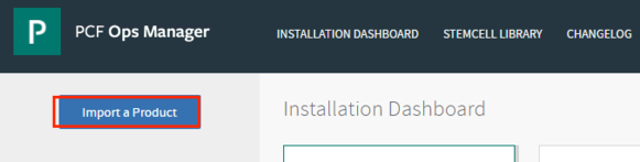
To import the PKS Tile, go to the home page of Ops Manager and click “Import a Product” and select the PKS package to begin the import process in to ops manager , it takes some time since this is a 4+GB appliance.

2.png

Once the PKS Tile has been successfully imported, go ahead and click on the “plus” sign to add the PKS Tile which will make it available for us to start configuring. After that, Click the orange Pivotal Container Service tile to start the configuration process.

12

Assign AZ and Networks

  • Here we will place the PKS API vm in the Management AZ and on the PKS Management Network that we have created on dvs in previous posts.
  • Choose Network which PKS API VM will use to connect to Network , in our case it is management network.
  • First time installation of PKS does not apply “Service Network” but we need to choose a network , for this installation i have created a NSX-T LS called “k8s” for Service network and i can use this in future, you can also create or specify “pks-mgmt” as this does not apply on new installation.
  • 3

Configure PKS API

  • Generate a wild card certificate for PKS API by selecting Generate RSA Certificate and create a DNS record.
  • Worker VM Max in Flight:  This makes sure how many instances of a component (non-canary worker) can start simultaneously when a cluster is created or resized. The variable defaults to 1 , which means that only one component starts at a time.
  • 4

Create Plans

Basically a plan defines a set of resource types used for deploying clusters. You can configure up to three plans in GUI. You must configure Plan 1.

  • Create multiple plans based on your needs like you can have master either 1 or 3.
  • you can choose to deploy number of worker VMs for each cluster and as per documentation worker nodes upto 200 has been tested but this number can go beyond 200 but sizing needs to be planned based on the other factors (like application and its requirement etc)
  • Availability Zone – Select one or more AZs for the Kubernetes clusters deployed by PKS for Master and same setting you need to configure for worker nodes and if you choose multiple AZ , then equal number of worker node will get deployed across AZs
  • Errand VM Type – select the size of the VM that contains the errand. The smallest instance may be sufficient, as the only errand running on this VM is the one that applies the Default Cluster App YAML configuration.
  • To allow users to create pods with privileged containers, select the Enable Privileged Containers – Use with caution because privileged containers is a container running as privileged essentially disables the security mechanisms provided by Docker and allows code to run on the underlying system.
  • Disable DenyEscalatingExec – This will disable Admission Control.
    • 56

Create Plan 2 and Plan3 or just choose Inactive and create them later but remember PKS does not support changing the number of master/etcd nodes for plans with existing deployed clusters.

Configure Kubernetes Cloud Provider (IAAS Provider)

Here you will configure your IAAS where all these VMs will get deployed and in my case this is vSphere based cloud but now PKS supports forAWS, GCP and Azure.

  • Enter vCenter Details like Name , Credentials , data store names etc..

8

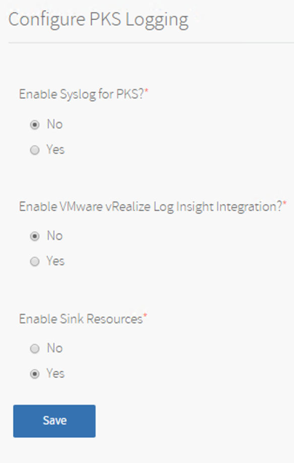
Configure PKS Logging

  • Logging is optional and can be configured with vRealize Log Insight , for my Lab i am leaving it default.
  • To enable clusters to drain app logs to sinks using SYSLOG://, select the Enable Sink Resources checkbox.
  • 9

Configure Networking for Kubernetes Clusters

NSX Manager Super User Principal Identity Certificate – As per NSX-T documentation , a principal can be an NSX-T component or a third-party application such open stack or PKS. With a principal identity, a principal can use the identity name to create an object and ensure that only an entity with the same identity name can modify or delete the object (except Enterprise Admin). A principal identity can only be created or deleted using the NSX-T API. However, you can view principal identities through the NSX Manager UI.

We will have to create a user id and that user, id PKS API uses the NSX Manager superuser principal identity to communicate with NSX-T to create, delete, and modify networking resources for Kubernetes cluster nodes. Follow the steps here to create it.

  • Choose NSX-T as  Networking Interface
  • Specify NSX Manager hostname and generate the certificate as per above step.
  • 10
  • Pods IP Block ID – Here enter the UUID of the IP block to be used for Kubernetes pods. PKS allocates IP addresses for the pods when they are created in Kubernetes. every time a namespace is created in Kubernetes, a subnet from this IP block is allocated.
  • Nodes IP Block ID – Here enter the UUID of the IP block to be used for Kubernetes nodes. PKS allocates IP addresses for the nodes when they are created in Kubernetes. The node networks are created on a separate IP address space from the pod networks.
  • 11.png
  • T0 Router ID – Here enter the  T0 router UUID.
  • 12.png
  • Floating IP Pool ID – Here enter the ID that you created for load balancer VIPs. PKS uses these floating IP pool to allocate IP addresses to the load balancers created for each of the clusters. The load balancer routes the API requests to the master nodes and the data plane.
  • 13.png
  • Node DNS – Specify Node DNS Server Name , ensure Nodes are reachable to DNS servers.
  • vSphere Cluster Names – Here enter a comma-separated list of the vSphere clusters where you will deploy Kubernetes clusters. The NSX-T pre-check errand uses this field to verify that the hosts from the specified clusters are available in NSX-T
  • HTTP/HTTPS Proxy – Optional
  • 14.png

Configure User Account and Authentication (UAA)

Before users can log in and use the PKS CLI, you must configure PKS API access with UAA. You use the UAA Command Line Interface (UAAC) to target the UAA server and request an access token for the UAA admin user. If your request is successful, the UAA server returns the access token. The UAA admin access token authorizes you to make requests to the PKS API using the PKS CLI and grant cluster access to new or existing users.

  • Leaving setting default with some timer changes
  • 15

Monitoring

You can monitor kubernetes cluster and pods using VMware Wavefront , which i will be covering in a separate post.

  • For now leave it default.

Usage Data

VMware’s Customer Experience Improvement Program (CEIP) and the Pivotal Telemetry Program (Telemetry)  program.

  • choose based in your preference.

Errands

Errands are scripts that run at designated points during an installation.

  • Since we are running PKS with NSX-T , we must need to verify our NSX-T configuration.
  • 16.png

Resource Config for PKS VM

Edit resources used by the Pivotal Container Service job and if there are timeouts while accessing PKS API VM , use high resource VM Type , for this LAB i am going with Default.

  • Leave it default.
  • 17.png

Missing Stemcell

A stemcell is a versioned Operating System image wrapped with IaaS specific packaging.A typical stemcell contains a bare minimum OS skeleton with a few common utilities pre-installed, a BOSH Agent, and a few configuration files to securely configure the OS by default. For example: with vSphere, the official stemcell for Ubuntu Trusty is an approximately 500MB VMDK file.

Click on missing stemcell link which will take you to StemCell Library. Here you can see PKS requires stemcell 170.15 , since i have already downloaded thats the reason it is showing 170.25 in the deployed section but in new installation cases it will show none  deployed. Click IMPORT STEMCELL and choose a stemcell which can be downloaded from Here to import.

18.png

Apply Changes

Return to Ops Manager installation Dashboard and click on “Review Pending Changes” and finally “Apply Changes” , this will go ahead and deploy PKS API VM at your IAAS location which you have chosen while configuring PKS tile.

14.png

and if the configuration of the tile is correct , around after 30 minute , you will see a successful message that deployment has been completed , which gives very nice feeling that your hard work  and dedication resulting success (for me it failed couple of time because of storage/network and resource issues).

To identify which VM has been deployed , you can check custom attributes or go back to  the Installation Dashboard, click the PKS tile then go to the Status tab. Here we can see the IP address of our PKS API , also notice CID which is VM name in vCenter inventory. also you can see the health of the PKS VM.

1920

This completes the PKS VM deployment procedure. in the next post we will deploy kubernetes Cluster.


vCloud Director 9.7 Portal Custom Branding

Much awaited feature for cloud provider to match thier corporate  standards and to create a fully custom cloud experience, now with release on vCloud Director 9.7 you can set the logo and the theme for your vCloud Director Service Provider Admin Portal and also now you can customize the vCloud Director Tenant Portal of each tenants . In addition, you can modify and add custom links to the two upper right menus in the vCloud Director provider and tenant portals.

Provider Portal Branding

vCloud Director 9.7 UI can be modified for the following elements:

  • Portal name
  • Portal color
  • Portal theme (vCloud Director contains two themes – default and dark.)
  • Logo & Browser icon

Customize Portal Name ,Portal Color and Portal Theme

To configure the Cloud Provider Portal Branding , make a PUT request to vCloud Director end point as below:

  • PUThttps://<vCD Url>/cloudapi/branding
  • BODY – {
    “portalName”: “string”,
    “portalColor”: “string”,
    “selectedTheme”: {
    “themeType”: “string”,
    “name”: “string”
    },
    “customLinks”: [
    {
    “name”: “string”,
    “menuItemType”: “link”,
    “url”: “string”
    }
    ]
    }
  • Headers
    • 2.png

Here is my API call using Postman client:

1.png

Customize Logo

To change the Logo, here is the procedure for API

  • Headers
    • 4.png
  • PUT
  • Body – This is bit tricky since we need to upload an image as a body.
    • In Postman client inside “Body” click on “Binary” which will allow you to choose file as body. select your logo.
    • 5.png

Customize Icon

To customize the icon, follow this API call and procedure.

  • Headers
    • 9.png
  • PUT
  • Body – same as above section , choose a image
    • 10.png

so after running above API calls , here is what my vCloud Director provider portal looks like.

678.png

Tenant Portal Branding

As we did above similarly we can now fully customize Tenant Portal

Customize Portal Name ,Portal Color and Portal Theme

To configure the Cloud Provider Portal Branding , make a PUT request to vCloud Director end point in to tenant organisation as below: ( T1 is my org Name)

  • PUThttps://<vCD Url>/cloudapi/branding/tenant/T1
  • BODY – {
    “portalName”: “string”,
    “portalColor”: “string”,
    “selectedTheme”: {
    “themeType”: “string”,
    “name”: “string”
    },
    “customLinks”: [
    {
    “name”: “string”,
    “menuItemType”: “link”,
    “url”: “string”
    }
    ]
    }
  • Headers
    • 11.png

Here is my API call using Postman client:

12.png

Customize Logo

To change the Logo, here is the procedure for API

  • Headers
    • 4.png
  • PUT
  • Body – As said above ,this is bit tricky since we need to upload an image as a body.
    • In Postman client inside “Body” click on “Binary” which will allow you to choose file as body, select your logo.
    • 14.png

Once i have done with above API calls, this is how my Tenant portal look like for “T1” organisation.

15.png

For a particular tenant, you can selectively override any combination of the portal name, background color, logo, icon, theme, and custom links. Any value that you do not set uses the corresponding system default value.

This completes feature walk through of Provider and Tenant custom branding options available now with vCD9.7.