Installing and Configuring VMware vCloud Availability for Cloud-to-Cloud DR – Part1

Some time back VMware has released much needed Cloud to Cloud DR solution for vCloud Director workloads for both VM and vAPP level. By using this solution Cloud Provider can build native vCD based Cloud to Cloud DR/Migration solution.

In this post we will get to know the Capabilities , Components , Installation and Configuration procedure of vCloud Availability for Cloud-to-Cloud DR solution.

  • This solution provides Multi-tenanted Self-service protection and failover workflows per virtual machine and vAppn between vCD sites.
  • Single Installation package based on Photon OS with capability of each deployment of this solution can act both as source and recovery vCD sites.
  • Symmetrical replication, can be started from either the source or the recovery vCD site.
  • Secure tunneling using TCP Proxy with built-in ability of encryption or encryption and compression of replication traffic.

Deployment Model 

There are three Roles that vCAv-C2C has:

  • Replication Manager Node with vCD Support

    • This Role Deploys vCloud Availability Replication Manager service and a vCloud Availability vApp Replication Service/Manager service in a single appliance.
  • Replicator Node (There is another Role called Large Replicator available , this can be deployed in Large Deployments.)

    • This Role deploys dedicated vCloud Availability Replicator appliance.
  • Tunnel Node

    • This Roles Deploy Tunnel Node. vCAv for C2C DR requires that each component on a local site has bidirectional TCP connectivity to each component on the remote site. If bidirectional connections between sites are not a problem , you do not need to configure Cloud-to-Cloud Tunneling. If you, however, configure Cloud-to-Cloud Tunneling, you must provide connectivity between thevCloud Availability Tunnel appliances on each site. After you configure the vCloud Availability Tunnel appliances, all other traffic goes through the vCloud Availability Tunnelappliances.

For POC purpose ,  we can deploy the simple architecture where all above three vCloud Availability for Cloud-to-Cloud DR services will be deployed and configured on a single appliance. This is called “Combined Mode

For production deployment, you must deploy and configure each service on a dedicated appliance.

Node Sizing:

Node Type vCPU Memory Disk
Replication Manager 4 6 GB 10 GB
Replication Node 2 4 GB 10 GB
Tunnel Node 2 4 GB 10 GB
Largre Replication Node 4 6 GB 10 GB

Requirements:

Lets Deploy vCAv-C2C on our First Site , this will be “Combined Role” installation.

Download the OVF from here, and deploy in to your  management cluster , where all other cloud components are deployed.

1.png

Browse and Select the Downloaded OVA

3

2

Choose your Data Center

4

Choose your Cluster 5

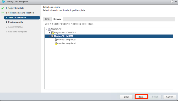
Review the “Product Information” and ensure we have chosen the right appliance.

6

“Accept” License Agreement”

7

Here is the most important selection , for Part1 we will choose “Combined” and when i will do second site we will do individual deployment.

8

Choose your Storage

9

Select appropriate Network and IP version.

10

Enter lots of information around IP, subnet , appliance Paasword etc..

11

Verify Summary of information we have filled/chosen and Click “Finish” to deploy appliance.

12

Once appliance get deployed , take a console and list down you IP address to manage.

13

Use the IP address and browse to Configure the appliance and Click on Links section

14

Log in to the portal

15

Configure a vCloud Availability Replicator

On a Web browser, Login to https://Appliance-IP-address:8043 , in My Case https://192.168.110.96:8043 and Click on – VMware vCloud Availability Replicator Configuration Portal.

replicator1.1.png

This will take you to login using the root password that you set during the OVA deployment. The Change Appliance Root Password pane opens. Change the initial appliance password and click Next.

replicator1.2.png

The Setup Lookup service pane opens. enter valid lookup service in this  https://Appliance-IP-address:port-number/lookupservice/sdk and Click Next.Lookup1

Review the lookup service certificate details and click AcceptTo complete the initial vCloud Availability Replicator configuration, click Finish. You are redirected to the vCloud Availability Replicator health status page.

lookuph1.png

Configure a vCloud Availability Replication Manager

On a Web browser, Login to https://Appliance-IP-address:8044 , in My Case https://192.168.110.96:8044 and Click on – VMware vCloud Replication Manager Configuration Portal

rmc1.pngThis will take you to login in with the appliance root password that we set during the initial vCloud Availability Replicator configuration. You will be redirected to the vCloud Availability Replication Manager health status page with an error that Lookup service settings are missing. we again need to setup lookup service. go to Configuration > Set lookup service.

lookuprmc2.pngAccept Certificate and now health in Diagnostic tab should be green.

Configure a vCloud Availability vApp Replication Service/Manager


On a Web browser, Login to https://Appliance-IP-address:8046 , in My Case https://192.168.110.96:8046 and Click on – VMware vCloud Availability vApp Replication Manager Configuration Portal

Repm1.png

This will take you to login in with the appliance root password that we set during the initial vCloud Availability Replicator configuration.  You will be redirected to the vCloud Availability vApp Replication Service/Manager initial configuration wizard.

Enter a Site Name and Site Description, and click Next.

16

Enter a Lookup service address and click Next.

18

Review  and Accept lookup service certificate.

19

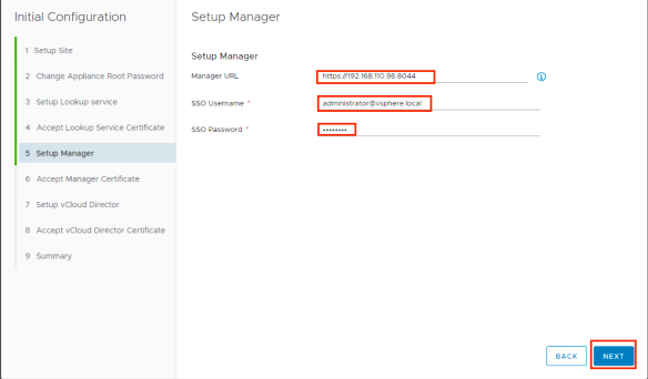
Set up the vCloud Availability Replication Manager.

  • Enter a Manager URL in the following format: https://Manager-IP-Address:8044
  • when Deploying combined appliance deployment type , Setup Manager URL is not mandatory.
  • Enter SSO user name and SSO password and click Next.

202122

Review  and Accept certificate.

Now let’s Set up vCloud Director. in Our case we are going to do “Manual” Setup.

  • Enter vCD URL.
  • Enter vCloud Director system administrator user name and password , this will perform all management operations.
  • Click Next.

23

Review  and Accept certificate.

24

Review the vCloud Availability vApp Replication Service/Manager configuration Summary and click Finish.

25

Verify that the vCloud Availability vApp Replication Service/Manager service is successfully configured.

26

Configure a vCloud Availability Portal

First ensure that below service are successfully configured

  • vCloud Availability vApp Replication Service/Manager
  • vCloud Availability Portal
  • vCloud Configuration Portal

In a Web browser, go to the vCloud Configuration Portal at https://Appliance-IP-Address:5480 and Log in.

av1.png

In vApp Replication Manager/vCD connection tab, enter the vCloud Availability vApp Replication Service/Manager and vCloud Director details and click Connect.

AV2

Accept Certificate

av3

Connection succeeded message appears.vCloud Director Base URL and Web Console addresses appear. Click on “Test”

av4

Test Result Pop-up , Click on Done and Click on Next

av5av6

Database connection tab, set up a database. we are going to use Embedded database.( if Distributed deployment then it is hosted on vCloud Availability Portal VM) , Click Test

av7.png

After Successful verification , succeeded message appears , Click Next.

av8.png

In the Portal Service Configuration tab, configure the vCloud Availability Portal Service.

  • Port , if you want to change , change it but ensure you also update firewall rules
  • Replace Certificate , if you want external certificate (ensure that the certificate .pem file contains both a private key and certificate)

Click on Start Service.

av9

Popup window with progress appears , verify configuration has been completed successfully. Click Done.

av10

You are redirected to the vCloud Configuration Portal Home page.

av11

This Completes Primary Site configuration. Let’s verify by logging on vCAv-C2C using tenant Credentials..

login1login2

i will be configuring the second site and will start pairing in next Post.

Some Important Service URLs

Service Management  Address and Port
vCloud Availability Replication Manager https://Appliance-IP-Address:8044
vCloud Availability Replicator https://Appliance-IP-Address:8043
vCloud Availability vApp Replication Service/Manager https://Appliance-IP-Address:8046
vCloud Availability Portal https://Appliance-IP-Address:8443
vCloud Configuration Portal https://Appliance-IP-Address:5480
vCloud Availability Tunnel https://Appliance-IP-Address:8047

Happy Learning 🙂

Deploy VMware Cloud Foundation on IBM Cloud – Part -2

In the Part-1 , we understood the feature, requirements and service available on VCF platform. in this post i will show you how to deploy VCF on IBM Cloud. lets start..

Some considerations for VCF on IBM Cloud

  •  (DFW) – You must configure rules for all communications from the IBM CloudDriver and the SDDC Manager virtual machines (VMs) to allow all protocols to communicate on the IP addresses 10.0.0.0/8 and 161.26.0.0/16.
  • (DFW) – You must create a DFW rule that allows for HTTPS traffic from the IBM Cloud Driver VM to any destination.
  • (DFW) – The DFW rule must come before any other rules that would block traffic to or from these VMs.
  • Do not change the NSX Manager password. You can find this password on the Summary tab of the instance details page in the IBM Cloud for VMware Solutions console.
  • You can change passwords for NSX Controllers.
  • Do not change the password for the management VMware NSX Edge Services Gateway (ESG)

During VCF deployment, VMWare NSX is ordered, installed, licensed, and configured in your instance. Also, NSX Manager, NSX Controllers, and NSX Transport Zone are set up, and each ESXi server is configured with the NSX components.

However, if your workload VMs need to communicate with each other and to access the Internet, it is your responsibility to configure NSX for use by your VMs.

Ordering VCF:

When you order a VCF instance, you must specify the following settings under System.

Instance type

You can deploy the instance as a primary (single) instance in your environment, or deploy the instance in a multi-site configuration by linking it with an existing primary instance for high availability. let’s start with our first VCF instance and Click on Primary

1.png


it will take to you next window as below to enter below details.

23

Instance name

The instance name must meet the following requirements:

  • Only alphanumeric and dash (-) characters are allowed.
  • The instance name must start and end with an alphanumeric character.
  • The maximum length of the instance name is 10 characters.
  • The instance name must be unique within your account.

Domain name

The root domain name must meet the following requirements:

  • Only alphanumeric and dash (-) characters are allowed.
  • The domain name must consist of two or more strings that are separated by period (.)
  • Each string in the domain name must start with an alphabetic character and end with an alphanumeric character.
  • The last string in the domain name can contain only alphabetic characters.
  • The length of the last string in the domain name must be in the range 2 – 24 characters.
  • The maximum length of the FQDN (Fully Qualified Domain Name) for hosts and VMs (virtual machines) is 50 characters. Domain names must accomodate for this maximum length.

Subdomain prefix

The subdomain prefix must meet the following requirements:

  • Only alphanumeric and dash (-) characters are allowed.
  • The subdomain prefix must start and end with an alphanumeric character.
  • The maximum length of the subdomain prefix is 10 characters.
  • The subdomain prefix must be unique within your account.

Host name prefix

The host name prefix must meet the following requirements:

  • Only alphanumeric and dash (-) characters are allowed.
  • The host name prefix must start and end with an alphanumeric character.
  • The maximum length of the host name prefix is 10 characters.

Bare Metal Server configuration

You can select a Bare Metal Server configuration depending on your requirements:

  • Small (Dual Intel Xeon E5-2650 v4 / 24 cores total, 2.20 GHz / 128 GB RAM / 12 disks)
  • Large (Dual Intel Xeon E5-2690 v4 / 28 cores total, 2.60 GHz / 512 GB RAM / 12 disks)
  • User customized: you can specify the CPU model and RAM for the bare metal server
  • Item Options
    CPU Dual Intel Xeon E5-2620 v4 / 16 cores total, 2.10 GHz
    Dual Intel Xeon E5-2650 v4 / 24 cores total, 2.20 GHz
    Dual Intel Xeon E5-2690 v4 / 28 cores total, 2.60 GHz
    RAM 64 GB, 128 GB, 256 GB, 384 GB, 512 GB, 768 GB, 1.5 TB

Data center location

You must select the IBM Cloud Data Center where the instance is to be hosted. Only the data centers that meet the Bare Metal Server specification are displayed.

Storage settings

The storage settings for the Small and Large standardized Bare Metal Server configurations cannot be changed:

  • For the Small Bare Metal Server configuration, two disk drives of 1.9 TB SSD SED are ordered.
  • For the Large Bare Metal Server configuration, four disk drives of 3.8 TB SSD SED are ordered.

If you selected the User customized Bare Metal Server configuration, you can customize the VMware vSAN storage for your instance by specifying the following settings under vSAN Storage:

Number of vSAN Capacity Disks

Specify the number of disk drives for the storage that you want to add.

Disk Type and Size for vSAN Capacity Disks

Select the type and capacity that meets your storage needs.

Licensing

When you order a VCF instance, you can also order the appropriate component licenses or Bring Your Own License (BYOL):

  • vCenter Server License – Standard
  • vSphere License – Enterprise Plus
  • NSX License – Enterprise
  • vSAN License: choose between Advanced and Enterprise edition

4.png

5.png

Once you filled the required data , click on the next , this will take you to Licenses page , here you have two options:

  • If you want new licenses to be purchased on your behalf, select Include with purchase for the components. For vSAN license, also select the license edition.
  • If you want to use your own VMware license for a component, select I will provide and enter the license key string for the component.

7.png

Click Next and that will take you to services pages where you can choose additional like:

VEEAM , F5 , FortiGate and Zero

8.png

Click Next and that will take you to Summary Page:

  • Review the settings for the instance.
  • Click the link or links of the terms that apply to your order, and ensure that you agree with these terms before you order the instance.
  • Review the estimated cost of the instance by clicking the price link under Estimated Cost. To save or print your order summary, click the Print or Download icon on the upper right of the PDF window.

9.png

Click Place Order.

The deployment of the instance starts automatically. You receive confirmation that the order is being processed and you can check the status of the deployment by viewing the instance details. When the instance is ready to use, the status of the instance is changed to Ready to Use and you receive a notification by email.

10.png

Next is to order a secondary instance, the VMware vSphere Web Client for the primary instance (linked to the secondary one) might be restarted after your secondary instance order is completed. View the access information for the instance-related components. These passwords are initial passwords that are generated by the system.

  • AD/DNS server IP: The IP address of the AD server.
  • AD/DNS server FQDN: The AD/DNS server fully qualified domain name.
  • AD/DNS server (Remote desktop): The user name and password that you can use to access the AD server via a remote desktop connection.
  • NSX Manager IP: The IP address of the NSX Manager.
  • NSX Manager FQDN: The NSX Manager fully qualified domain name (FQDN).
  • NSX Manager (HTTP): The user name and password that you can use to access the NSX Manager web console.
  • NSX Manager (SSH): The user name and password that you can use to access the NSX Manager VM via SSH connection.
  • PSC IP: The IP address of the Platform Services Controller (PSC).
  • PSC FQDN: The PSC fully qualified domain name (FQDN).
  • PSC (SSH): The user name and password that you can use to access the PSC VM via SSH connection.
  • PSC (ADMIN): The VMware vCenter Single Sign-On user name and password that you can use to access the PSC web console.
  • vCenter IP: The IP address of the vCenter Server.
  • vCenter FQDN: The vCenter Server fully qualified domain name (FQDN).
  • vCenter (SSH): The user name and password that you can use to access the vCenter Server VM via SSH connection.
  • vCenter (ADMIN): The VMware vCenter Single Sign-On user name and password that you can use to log in to the vCenter Server by using the vSphere Web Client.

11.png

that completes our first VCF deployment. Happy Learning 🙂


vRA7.3 – T-Shirt Size BluePrints

While I was working on various vRA deployment whether it is 6.x , 7.0 , 7.1 and 7.2 and many of my customers was looking for T-Shirt sizing VMs and I had to write vRO workflow with custom properties to ensure that customer get desired T-shirt sizing deployed VMs.

Now with the release of vRA7.3 , this is Out of the box available , Now you can have traditional blue print where user will chose number of CPU’s and Memory etc…or you can have blueprints where user chooses T-shirt size(like Small , Medium and Large )  deployment. obviously these parameterized blueprints will help us in reducing blueprint sprawls.

In vRA 7.3 VMware Introduced component profiles for defining size and image attributes , which will going to help us out in creating T-Shirt size blue prints and further we can trigger approval policies to size or image conditions.

In this post I will create a simple blue print by defining size and image attributes.

Let’s first Define Component Profile Size:

  • Log in to the vRealize Automation console as an administrator with tenant administrator and IaaS administrator access rights.
  • Select Administration > Property Dictionary > Component Profiles.2
  • Click Size in the Name Column.
  • Click the Value Sets tab3
  • For defining a new value set, Click New and configure the Size settings.4
  • Enter the Values based on your defined sizes., Here I am creating three sizes:

    Small: 1 vCPU, 4 GB RAM and 10 GB Storage.

    Medium: 2 vCPU, 8 GB RAM and 20 GB Storage.

    Large: 4 vCPU, 16 GB RAM and 40 GB Storage

    5

  • Once defined all the value sets click Finish , and we will have three value sets defined.

    22

    Next is the image profile.Now Click on Image

  • Click Size in the Name Column.7
  • 8
  • Click on Value Set and then Click on New

    Enter Display Name

    Enter Status as Active

    Enter Action as Clone and we will be cloning from a template

    Enter Blueprint Type as Server

    Enter CloneFrom as “your vSphere Template”

    Enter Customization Spec as “Same name as you have created in vCenter”

    Enter Provisioning workflow as Cloneworkflow9.png

  • I am creating Image Value Sets for three operating systems

    Windows 2012

    Windows 2016

    Cent OS

  • 10
  • Once created all, Click Finish.

We are done with Value Set of size and Image.

Now let’s create a Blueprint to use these Value Sets.

  • Log in as an infrastructure architect.

Click the Design tab.

Click New.

  • In the New Blueprint window:
  • Type the name of the blueprint in the Name text box.
  • The Identifier text box will be auto-populated.
  • Type the purpose of the blueprint in the optional Description text box.
  • Select the Archive
  • Select the Minimum and Maximum Lease
  • On the NSX Settings tab, select Transport zone and Routed gateway reservation policy as applicable.
  • Click OK.

11

  • Click Machine Types in the left top navigation panel.You will see a list of all the machine types below.
  • Drag and drop a VMware vSphere® machine onto the main canvas.

12.png

  • Type the name of the VM component in the ID text box.
  • Leave the Machine Prefix as Use Group Default. The host name will be assigned based on the machine prefix defined in your business group.
  • Select the Minimum and Maximum13.png
  • Select Network & Security in the top left pane.
  • Drag and drop Existing Network on the main canvas.

    14

  • In the Select Network Profile dialog box, select the network profile to use in your blueprint. Click OK and Click Save.
  • Select the vSphere machine again on the main canvas. On the Network tab:
    • Click New.
    • Select the Network.
    • For Assignment Type, select Static IP or DHCP.15.png
  • Next Important to Achieve t-shirt sizing, go to Profile
    • Click on ADD
    • 16.png
    • choose your component profile which we have created in previous steps and Click OK.
    • 17
    • Then Click on Size and Choose Edit Value Sets and Choose all the Value sets that you want and a default value sets
    • 18a
    • 17-a.png
    • Click Ok and Publish the Blueprint.
    • 18.png
    • 19
    • After configuration of entitlement , you will get Blueprint is in Service Catalog.
    • 22a.png
    • Let’s Request a VM using T-Shirt Sizing
    • Choose Image Set that we have created in Image Value Sets.
    • 20
    • Choose Size that we have created in size Value Sets.21

Happy learning 🙂


vSAN 6.6 Released

vSAN6.6 just has been released to download.

vSAN 6.6 is a major new release that requires a full upgrade. We have to perform  following tasks to complete the upgrade to vSAN 6.6:

  1. Upgrade the vCenter Server to vSphere 6.5.0d.
  2. Upgrade the ESXi hosts to vSphere 6.5.0d.
  3. Upgrade the vSAN on-disk format to version 5.0.

Note: Direct upgrade from vSphere 6.0 Update 3 to vSphere 6.5.0d and vSAN 6.6 is not supported.

Release notes are here.

Learn VMwareCloudFoundation – Part01

Starting a series of posts on Learning VMware Cloud Foundation , here is the first in the series…

Basically, it brings together vSphere, VSAN, and NSX into the next generation hyper-converged platform. product that brings all of these components together in an easy to deploy and consume manner is a new product called the SDDC Manager. SDDC Manager allows you to consume the entire stack as a unified single entity.

VMware Cloud Foundation can also be consumed both on premise on qualified hardware, and as a service from cloud partners,like IBM Soft Layer . Customer can now build a true hybrid cloud, linking the private and public cloud through this unified and common foundation across both environments.

1.JPG

Why to Choose VCF

Standard design – virtualization components like vSphere ESXi , vSAN , NSX   and management components like vCenter , NSX Manager , Controllers  are automatically deployed and configured according to a validated datacenter architecture based on  best practices. This will eliminate enterprises lengthy planning cycles for vSphere , NSX , vSAN , vROps , LI  design and deployment.

Fully Integrated stack – with VCF the VMware virtualization components like ESXi, vSAN, NSX and the management software like vCenter, LogInsight, vROps, SDDC Manager are combined into a single cloud infrastructure platform, that basically eliminating the need to rely on complex interop matrixes.

Automates Hardware and Software Bring-Up – Cloud Foundation automates the installation of the entire VMware software stack. Once the rack is installed and powered on and the networking is in place, SDDC Manager leverages its knowledge of the hardware
bill of materials and user-provided environmental information (e.g. DNS, IP address pool, etc.) to initialize the rack. Time savings varies by customer, but software installation time is estimated to be reduced from several weeks to as little as two hours due to the automation of certain previously manual functions. These include provisioning workloads, including automated provisioning of networks, allocation of resources based on service needs, and provisioning of end points. When the process completes, the customer has a
virtual infrastructure ready to start deploying vSphere clusters and provisioning workloads.

Lifecycle management automation – Data center upgrades and patch management are typically manual, repetitive tasks that are prone to configuration and implementation errors. Validation testing of software and hardware firmware to ensure interoperability among components when one component is patched or upgraded requires extensive quality assurance testing in staging environments.

SDDC Manger provides built-in capabilities to automate the bring up, configuration, provisioning and patching/upgrades of the cloud infrastructure.Lifecycle management in SDDC Manager can be applied to the entire infrastructure or to specific workload domains and is designed to be non-disruptive to tenant virtual machines (VMs).

2.jpg

Integrates Management of Physical and Virtual Infrastructure – SDDC Manager understands the physical and logical topology of the software defined data center and the underlying components’ relation to each other, and efficiently monitors the infrastructure to detect potential risks, degradations and failures. SDDC Manager provides stateful alert management to prevent notification spam on problem detection. Each notification includes a clear description of the problem and provides remediation actions needed to restore service.

Components of VCF –

3

Physical Architecture of VCF

A VCF instance starts with a single rack, and scales up to 8 racks, each containing up to 32 hosts per rack. This gives us a total of 256 hosts per VCF instance. Each rack contains two top-of-rack (ToR) switches and a management switch, and racks 2-8 are connected to spine switches in the first or second rack. A VMware Cloud Foundation private cloud deployment is comprised of between one to eight physical racks. Each rack contains between 4 to 32 vSAN Ready Nodes, one management switch, and two Top-of-Rack (ToR) switches.In multi-rack configurations, a pair of redundant spine switches are added to provide for inter-rack connectivity.

4.jpg

Spine Switches

The Cloud Foundation system contains two spine switches. These switches extend the network fabric of the top of rack (ToR) switches between racks and are used for inter-rack connectivity only. The hardware vendor connects the available uplink ports of the ToR switches to the spine switches.
Spine switches are required only in multi-rack installations of Cloud Foundation and are placed in the second rack.

Management Switch

The management switch provides Out-Of-Band (OOB) connectivity to the baseboard management controller (BMC) on each server.The management network fabric does not carry vSphere management, vSAN, or vMotion traffic. That traffic resides on the network fabric created by the TOR and spine switches. As a result the management switch is a non-redundant component in the physical rack. If this switch goes down, some functionality such as monitoring may not be available until it comes back up. Workloads will continue to run, but the infrastructure associated with them cannot be modified or controlled.

Open Hardware Management System (OHMS) – On each management switch OHMS is running which is recently made open source. This is a Java runtime software agent that is invoked to manage physical hardware across the racks. SDDC Manager will communicate with OHMS to configure switches and hosts (Cisco API, CIMC, Dell, etc.). VMware has developed plugins for Arista and Cisco, but now this is open-source vendors can write their own plugins for other hardware platforms.

Top of Rack Switches

A physical rack contains two top of rack (ToR) switches, each of which has 48 10GE ports and at least 4*40GEuplink ports. The ToR and spine switches carry all network traffic from the servers including VM network,VM management, vSAN, and vMotion traffic. On rack 1 in a multi-rack Cloud Foundation, the ToRs also carry traffic to the enterprise network via two of the uplink ports. The ToR switches provide higher bandwidth as well as redundancy for continued operation in case one of the ToR switches goes down.If the installation has spine switches, two uplink ports from each ToR switch on each rack are connected to each spine switch.

Servers

A physical rack must contain a minimum of four dual-socket 1U. You can incrementally add servers to the rack up to a maximum of 32 servers.All servers within a rack must be of the same model and type. The disk size and storage configuration must be identical as well. Memory and CPU (e.g. per CPU core count) between servers can vary.

Management Domain

SDDC Manager configures the first four servers in each physical rack into an entity called the management domain. After you deploy Cloud Foundation, you can expand the management domain.The management domain manages the hosts in that rack. All disk drives are claimed by vSAN.The management domain contains the following:
vCenter Server Appliance(including both vCenter Server and Platform Services Controller as separate VMs) managing the vSphere cluster with HA and DRS enabled and the following VMs:
NSX Manager
vRealize Operations
vRealize Log Insight
SDDC Manager

5

Physical Network Connectivity

All hosts in a physical rack are connected to both the two ToR switches with 10Gb links. On each host, NIC port 1 is connected to ToR switch 1 and NIC port 2 is connected to ToR switch 2 with Link Aggregation (LAG).
The BMC on each host is connected to the management switch over a 1G connection. This connection is used for OOB management. Both ToR switches are further connected to a pair of spine switches in a dual-LAG configuration using 40 G links. The spine switches are an aggregation layer for connecting multiple racks.

Physical Storage Connectivity

The primary source of storage for Cloud Foundation is vSAN. All disks are claimed by vSAN for storage.
The amount of available physical storage in workload domains depends on the number of physical hosts.Storage traffic is carried over the 10Gbps links between the hosts and ToR switches. All vSAN member hosts communicate over this 10Gbps network.

vSphere Network I/O Control (NIOC) can be enabled to allow network resource management to use network resource pools to prioritize network traffic by type.

This covers Hardware Architecture of the VMware Cloud Foundation , Next i will be covering software components of VCF. till the time Happy Learning 🙂


vCenter 6.5 HA Architecture Overview

A vCenter HA cluster consists of three vCenter Server Appliance instances. The first instance, initially used as the Active node and is cloned twice to a Passive node and to a Witness node. Together, the three nodes provide an active-passive fail over solution.

Deploying each of the nodes on a different ESXi instance protects against hardware failure. Adding the three ESXi hosts to a DRS cluster can further protect your environment.When vCenter HA configuration is complete, only the Active node has an active management interface (public IP). The three nodes communicate over a private network called vCenter HA network that is set up as part of configuration. The Active node and the Passive node are continuously replicating data.

vcenter_ha

All three nodes are necessary for the functioning of this feature. Compare the node responsibilities.

Active Node:

Runs the active vCenter Server Appliance instance
Uses a public IP address for the management interface
Uses the vCenter HA network for replication of data to the Passive node.
Uses the vCenter HA network to communicate with the Witness node.

Passive Node:

Is initially a clone of the Active node.
Constantly receives updates from and synchronizes state with the Active node over the vCenter HA network.
Automatically takes over the role of the Active node if a failure occurs.

Witness Node:

Is a lightweight clone of the Active node.
basically works as a quorum to protect against a split-brain situations.

Note:

  • vCenter HA network latency between Active, Passive, and Witness nodes must be less than 10 ms.
  • The vCenter HA network must be on a different subnet than the management network.
  • vCenter Server 6.5 is required.

I hope this will help you to plan your next vSphere upgrade with vCenter High Availability.

Happy Diwali 🙂


VMware vCenter Appliance (VCSA) 6.5 Now Running on PhotonOS

From vSphere 5.5 the VCSA was running on SLES, while the latest version of VCSA was running on SLES 11 but Starting with vSphere 6.5, the vCenter Server Appliance is now running on VMware’s own Photon OS, which is a Minimal Linux Container Host, optimized for running on the VMware platform.

ver

This is a great move by VMware to help simplify support and maintenance of OS/Appliance lifecycle, and streamline updates and patches. VMware no longer has to rely on SUSE Linux when trying to fine-tune the applications and dependencies and release any updates.

VCSA6.5 is running on Postgress database. It also has a management UI at port https://<IP address of appliance> :5480 which will allow you to monitor the database utilization and size along with CPU and Memory.

Additional benefits  of using Photon OS:

  • The OS comes Pre-hardened.
  • More than 80% reduction in disk space for OS.
  • 3-4 x reduction in kernel boot time vs. general-purpose kernel , will help you to boot up vCenter quickly in case of failures.

2.jpg


Happy Diwali 🙂

What’s New in vSphere 6.5?

Guys , Today VMware announced vSphere 6.5, here is the new feature list and enhancements…

Features which really excites me are as below:

Scale Enhancements – New configuration maximums to support even the largest app environments.

VMware vCenter Server® Appliance – The single control center and core building block for vSphere , VMware wants going forward every should use vCenter appliance and lots of efforts have been made to make it possible , Now Appliance support…

  • Native High Availability
    • Now vCenter Appliance  has High Availability which is a native HA solution built right into the appliance. Using an Active/Passive/Witness architecture, vCenter is no longer a single point of failure and can provide a 5-minute RTO. This HA capability is available out of the box and has no dependency on shared storage, RDMs, or external databases.

  • Vmware update Manager is now part of appliance.
    • integration of VMware Update Manager into the vCenter Server Appliance , so more separate windows based deployment required , Zero setup; embedded DB and Leverages VCSA HA and backup
  • Improved Appliance Management
    • Now user interface shows Network and Database statistics, disk space, and health in addition to CPU and memory statistics which reduces the reliance on using a command line interface for simple monitoring and operational tasks.

  • Native Backup and Restore
    • Appliance only , Now support simplified backup and restore with a new native file-based backup solution to external storage using HTTP , FTP or SCP protocols  and Restore the vCenter Server configuration to a fresh appliance.

NOTE – These new features are only available in the vCenter Server Appliance.

vSphere Client (HTML5 Web Client)

  • Clean, modern UI built on VMware’s new Clarity UI standards, No browser plugins to install/manage , Integrated into vCenter Server for 6.5 and Fully supports Enhanced Linked Mode.

vSphere Integrated Containers (VIC)

  • VIC extends vSphere capabilities to run container workloads and sits on top of vCenter, and integrates with the rest of the Vmware stack like NSX and vSAN.
  • VIC contains three parts, VIC engine which delivers virtual container host that provides native docker endpoint, developer can continue to use the familiar docker commands, the fact these docker containers are running in a virtual infrastructure is transparent to them, except for the benefit that their infrastructure resources like compute, storage can be expanded much more easily.
  • The second component is registry which provides enterprise private registry capability to give IT control over their intellectual property. This is an optional component, you can of course use docker or other registry of your choices.
  • The third component is container management portal which provide GUI, API and CLI interfaces to provision, manage and monitor containers.

Simplified HA Admission Control

  • Simplified configuration workflow
  • Additional Restart Priorities added – Highest , High , medium , low and Lowest

Proactive HA 

  • Detect hardware conditions of host components by receiving alerts from hardware vendor monitoring solution
    • Dell Openmanage
    • HP Insight Manager
    • Cisco UCS Manager
  • Notifications of host impacted, its current state, error causes, severity and physical remediation steps and vMotion VMs from partially degraded hosts to healthy hosts. ( this is configurable)
  • i think this is really awesome if configured properly.

Network-Aware DRS

  • Adds network bandwidth considerations by calculating host network saturation (Tx & Rx of connected physical uplinks)

Currently i am going through detailed feature list and will be sharing more soon , till that time Happy learning 🙂


Salting with Transparent Page Sharing

This week one of my customer asked me about TPS setting and he said TPS was very good now since it has been disabled what else can be done to achieve memory saving techniques in vSphere 6. so i hv explained him that TPS has been disabled for Inter-VM but Intra-VM is still working and there are few alternative ways by which you can enable Intra-VM TPS. so thought of sharing this with you all , to clarify what has been disabled and what is available and what can be done to achieve Intra-VM TPS.

So Basically Transparent page sharing allows multiple virtual machines to share pages when the pages are identical.In vSphere 6, intra-VM TPS ( pages within the VM )is enabled by default and inter-VM TPS (pages across VMs) is disabled by default, due to some security concerns as described in VMware KB2080735.

to over come the security issue , the concept of salting has been introduced, which can be used to control and manage the virtual machine participating in TPS. Earlier for two Virtual machines to share pages, the contents of the pages should be same. With the concept of salting, along with the content of the pages, the salt values for the two virtual machines should be same.

Salting is used to allow more granular management of the virtual machines participating in TPS than was previously possible. As per the original TPS implementation, multiple virtual machines could share pages when the contents of the pages were same. With the new salting settings, the virtual machines can share pages only if the salt value and contents of the pages are identical. A new host config option Mem.ShareForceSalting is introduced to enable or disable salting.

By default, salting is enabled (Mem.ShareForceSalting=2) and each virtual machine has a different salt. This means page sharing does not occur across the virtual machines (inter-VM TPS) and only happens inside a virtual machine (intra VM).

When salting is enabled (Mem.ShareForceSalting=1 or 2) in order to share a page between two virtual machines both salt and the content of the page must be same. A salt value is a configurable vmx option for each virtual machine. You can manually specify the salt values in the virtual machine’s vmx file with the new vmx option sched.mem.pshare.salt. If this option is not present in the virtual machine’s vmx file, then the value of vc.uuid vmx option is taken as the default value. Since the vc.uuid is unique to each virtual machine, by default TPS happens only among the pages belonging to a particular virtual machine (Intra-VM).If a group of virtual machines are considered trustworthy, it is possible to share pages among them by setting a common salt value for all those virtual machines (inter-VM).

The following table shows how different settings for TPS are used together to effect how TPS operates for individual virtual machines:

salt

Comments are welcome and Happy learning 🙂

My VCAP-DCD Exam experience

After a series of reschedules, finally when i again tried to reschedule yesterday, it did not allowed as i was trying to reschedule within 24 hours of scheduled, that is not allowed, so finally  I had to sit for VCAP-DCD exam this week and I passed it. I needed this exam passed to be eligible for VCDX path since I am already a VCAP-DCA since 2014. It was my second attempt after I failed VCAP-DCD back in middle of 2015. it was long time due but did not had courage to sit again as this is one of the hardest exam i have ever given. you get a design canvas and you have to fit lots of objects in that canvas and then connect with with various connectors and most important thing is that questions are so very trick and lots of design decisions hidden on those tricks words.

The content of certain questions are still completely disconnected from typical project realities but altogether it is now clear that exam creators want to test analytical and abstract thinking instead of checking against simple memorized content. That is the reason why I value VCAP exams so much.

It took a lot of time and a lot of effort but in the end it was worth it.

PowerActions for vSphere Web Client

PowerActions integrates the vSphere Web Client and PowerCLI to provide complex automation solutions from within the standard vSphere management client.

PowerActions is deployed as a plugin for the vSphere Web Client and will allow you to execute PowerCLI commands and scripts in a vSphere Web Client integrated Powershell console.

Furthermore, administrators will be able to enhance the native WebClient capabilities with actions and reports backed by PowerCLI scripts persisted on the vSphere Web Client. Have you ever wanted to “Right Click” an object in the web client and run a PowerCLI script? Now you can!

For example I as an Administrator will be able to define a new action for the VM objects presented in the Web client, describe/back this action with a PowerCLI script, save it in a script repository within the Web client and later re-use the newly defined action straight from the VM object context (right click) menu.

Or I as an Administrator can create a PowerCLI script that reports all VMs within a Data Center that have snapshots over 30 days old, save it in a script repository within the Web client and later execute this report straight from the Datacenter object context menu.

Or better yet, why not share your pre-written scripts with the rest of the vSphere admins in your environment by simply adjusting them to the correct format and adding them to the shared script folder.

PowerActions is a plugin for the vSphere Web Client – if you manage multiple Virtual Centers from a single web client instance it will work with all registered vCenters.

Download Here 

poweraction

DRS Doctor

DRS Doctor is a command line tool that can be used to diagnose DRS behavior in VMware vCenter clusters. When run against a DRS enabled cluster, it records information regarding the state of the cluster, the work load distribution, DRS moves, etc., in an easy to read log format.

The goal of DRS Doctor is to give VI admins better insight into DRS and the actions it performs. It is very useful for analyzing DRS actions and troubleshooting issues with very little overhead. This is also an easy way for support engineers to read into customer environments without having to rely on developers to debug DrmDump logs in order to troubleshoot simple DRS issues.

DRS Doctor connects to the vCenter server and tracks the list of cluster related tasks and actions. It also tracks DRS recommendations generated and reasons for each recommendation, which is currently only available in a hard-to-read format in DrmDump files. At the end of each log, it dumps the Host and VM resource consumption data to give a quick overview of cluster state. It also provides an operational audit at the end of each log file.

drs_doctor

Download Here

Prerequisites for Installation:

  • Requires Python 2.7.6 or higher
  • Requires Python modules “pyyaml” and “pyvmomi”

Note: The VMware vSphere API Python Bindings can be found here: https://github.com/vmware/pyvmomi

For Python versions less than 2.7.9, the pyVmomi version should be 5.5 (pip install pyvmomi==5.5.0.2014.1.1). If using Python 2.7.9+ the version 6.0 of pyvmomi can be used.

For certificate validation (SSL) support, Python 2.7.9 or above and pyVmomi 6.0 is required.

NOTE –  DRS must be in partially automated mode in order for DRS Doctor to work. If your cluster is in fully automated mode, DRS Doctor will automatically change the mode to partially automated mode and apply the load balancing recommendations based on the threshold configured. (It will act just as it would in fully automated mode.) *Note: If you close DRS doctor you will need to ensure that the DRS automation settings get reverted to fully-automated mode.

VMware vROps Manager Fundamentals [V6.2] – Free e-learning

This free e-learning cours demonstrates how VMware vRealize® Operations Manager™ delivers intelligent operations management from applications to infrastructure across physical, virtual, and cloud environments.

REGISTER HERE
– Explain how an analytics-based operational process addresses the challenges of IT      operations.
– Name the three main use cases for intelligent operations
– Describe how the architecture of vRealize Operations Manager supports scalability,         reliability, and extensibility
– Summarize the process to deploy vRealize Operations Manager
– Recognize how vRealize Operations Manager helps IT Operations: Optimize utilization
– Ensure performance and availability across the software-defined data center (SDDC)
Monitor heterogeneous data centers and hybrid clouds
– Browse for solutions to extend intelligent operations from applications to infrastructure across physical, virtual, and cloud environments